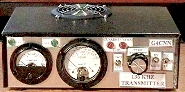

During the early months of 2000 I built G0MRF’s DDS VFO and now the “300 watt” transmitter. Then when we had some nice weather I put down a good earth mat consisting of 10 radials of 10 metres each and 3 earth rods 2metres deep. The radials have been buried a few inches using the garden spade and the earth rods are actually copper water pipe. I attached the garden hose to each pipe in turn and with the water flowing twisted and pushed them down into the soil, which is actually chalk here (part of the Chilterns). It took a while and sometimes I had to leave the water flowing for 10 minutes or so, but eventually they went down to the full depth.
One of my first contacts was Dave, G3YMC and I was quite astonished to receive S9 from him. However he is not that far away from me so it is really not that surprising.
The biggest problem I have, is that we are on the side of a hill, with the house at the bottom and the garden rises by 20 feet from the back of the house so that at the end of the garden one is at roof level. It seemed sensible to put the main pole as high up as possible, but the hill continues a bit beyond us and we are overlooked by 100 foot beech trees. The pole is only 7 metres, but with the hill it amounts to about 13 metres, still dwarfed by the trees of course. What I plan to do is to increase the height as much as possible, add a top loading coil like G3XDV ( it is built but looks too big and heavy) and add more top loading wires if I can find somewhere to attach them – perhaps train the squirrels to carry them up the big trees, hi!
The Tx includes a Power/SWR meter, but I also use an HF SWR meter, which is good for SWR, but no good for Power metering, not sensitive enough at LF, so I have built the RF ammeter from Technical Topics in the October Radcom. That is now working well, so I finally know how much power is going into the antenna (200 watts).
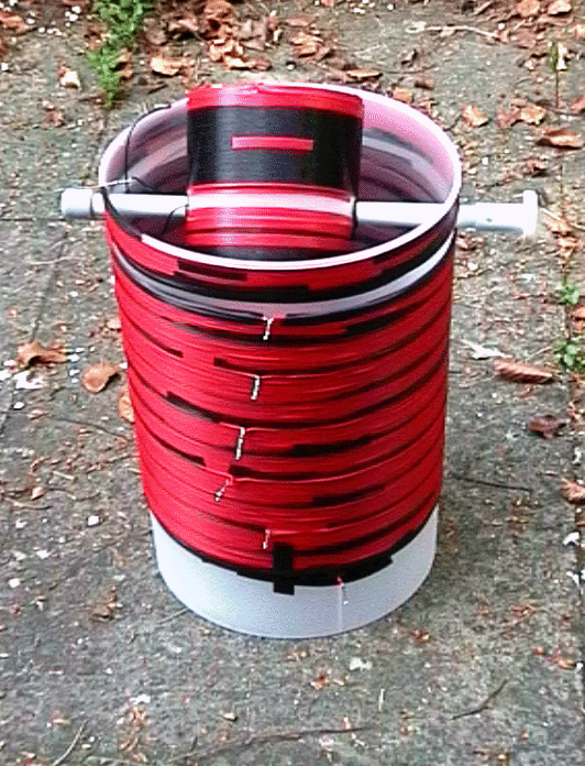
The antenna requires 4mH at 137 kHz to tune it and I have built a loading coil with a variometer using two polystyrene plastic bins for the main coil and a polystyrene toilet roll holder for the variometer coil. I calculated the inductance required from Rik Strobe’s formulae and designed the coils using G4FGQ’s Solenoid program. After building it, I measured the inductance of the loading coil between each pair of taps with the variometer coil at its maximum and minimum positions and after a few goes managed to arrange the taps to give complete coverage from 200 microhenries up to over 7mH. To keep the weather and the insects out of the loading coil and matching transformer, I cover them with garden refuse bags from Homebase and seal the joins with duck tape, which I have tested in the microwave to make sure it is a good insulator. You can still get to the handle of the variometer through the loose plastic. I have added a small scale to allow me to create a table of settings for different parts of the band.


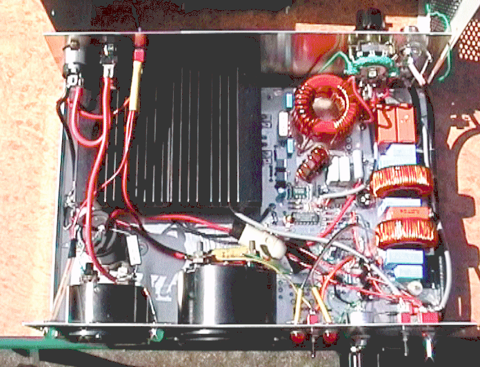
My version of the G0MRF 300/400 Watt Transmitter. Internal views shows the giant heat sink I fitted. A fan is mounted immediately above the heat sink, with a grill to the right of the PCB. As a result of which the pair of MOSFETs never get hot.

Loading coil and variometer for 136kHz made from two 25 litre plastic tubs, open end to open end, wound with the two insulated wires from 100 metres of 13A ring main cable. The view shows the lower half of the loading coil and the variometer, which is wound on a polystyrene toilet roll holder. I have since removed half of the turns on the variometer to make it less sensitive and easier to tune. It is now wound with 44 turns of 16/0.2 equipment wire. To keep the weather and the insects out of the loading coil and matching transformer (GW4ALG design), they sit in a shallow plastic planter on the patio and the whole thing is convered with garden refuse bags which fit tightly over the planter. It is easy to remove it if necessary to change the tappings or to adjust the variometer.

The Variometer is coupled to a coax feed line at the bottom at the fourth tap up and the antenna is taken from the top-most tap. To avoid direct coupling of the earth back into the shack and to match to the earth resistance of about 108 ohms to the 50 ohm coax, I use a 58mm 3C85 ferrite ring transformer. It is a modification of the GW4ALG design, with 30 turns on the primary and 46 turns on the secondary tapped at 39, 40, 41, 42, 43, 44 and 45 turns. The 6th tap gives a very close match to 50 ohms and an SWR of 1:1.