
Military Wireless in the Midlands Museum Virtual Site
A Paraset copy build
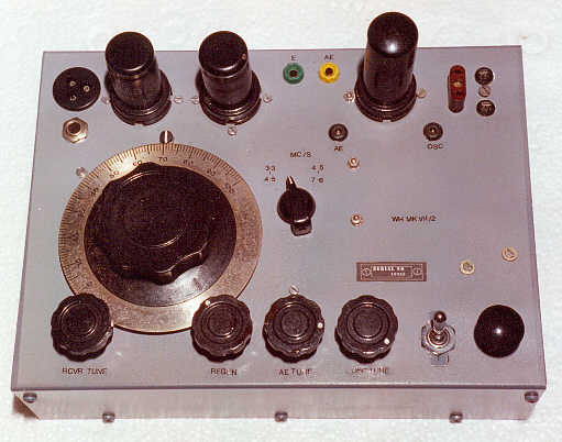
An original Wadden Mk7 Receiver Transmitter in wood case.
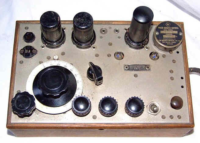
For more detailed pictures of the original set click here Original WW2 Paraset
Left: The start of the project, the panel received from Jos.
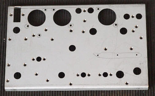
Right: Within ten mins I had fitted some bits..
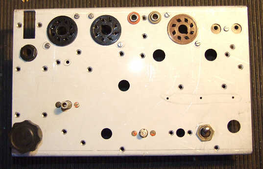
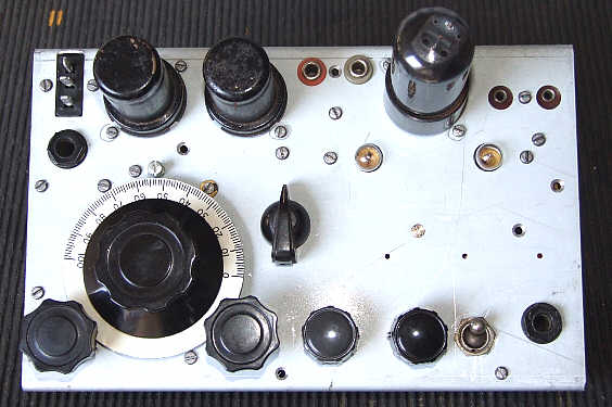
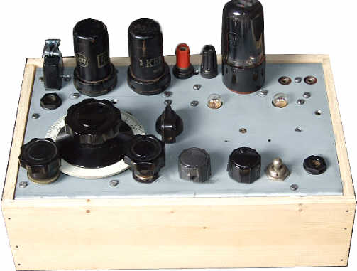
After a week the panel now looks like this...
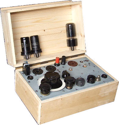
The Inside looks like this...
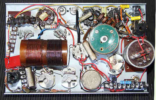
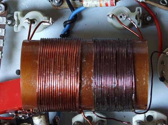
Left: The rx coil, a plug in coil from the R1082 slightly moddified, the audio o/p load a Command rx o/p transformer.

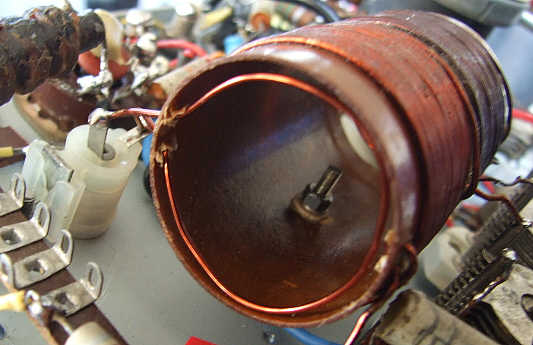
Right: The PA stage coil and tuning capacitors, this is wound on the outer of the R1082 coil.
Rx working fine and 5W out with about 365v ht on the transmitter.
So, all thats left is a couple of R's for the rx ht dropper, the bulbs for tuning and fabrication of case, painting etc etc.
Interesting. I noticed on someone else's Para web site they talked about the bulb indicators and power taken. I have now wired up the two lamps.
With 350v ht, no bulbs 5.1w ae bulb 2.2v 4.8w both bulbs 2.2v 4.3w
2v ae bulb and 6.3v pa bulb 4.5w (I can only find one 6.3v bulb but I guess if I fit it to ae then o/p would be about 4.8w or so)
So, seems best option is, tune for max, then unscrew pa bulb, re tweak for max on ae bulb then unscrew, for that last bit of puff out of the set.
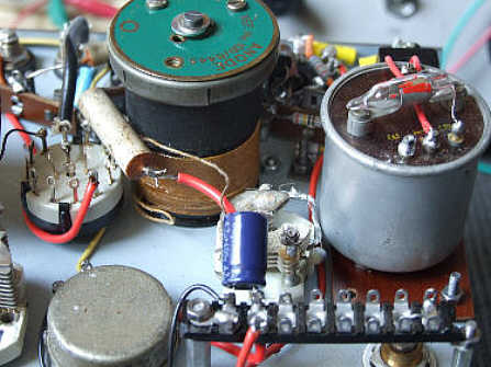
This is the pa indicator coupling loop.
and the two bulbs used for tuning of the transmitter.
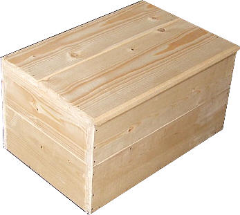
I had a go at making a wood case for the set..

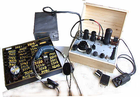
and finally................. the set in operation, 6L6 in the tx, the box of xtals being bigger that the actual set!
and a previous attempt at a Paraset copy.
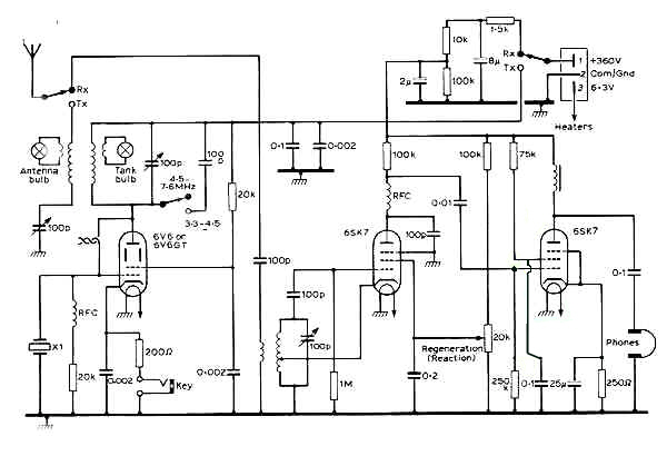
The basic Paraset circuit diagram.
see also MK XV Transmitter
Send an e-mail to: Ben Nock, G4BXD
(If link does not work on your PC then send email to: [email protected] )
********* Pictures by G4BXD are G4BXD copyright ********
With 350v ht, no bulbs 5.1w ae bulb 2.2v 4.8w both bulbs 2.2v 4.3w
2v ae bulb and 6.3v pa bulb 4.5w (I can only find one 6.3v bulb but I guess if I fit it to ae then o/p would be about 4.8w or so)
So, seems best option is, tune for max, then unscrew pa bulb, re tweak for max on ae bulb then unscrew, for that last bit of puff out of the set.
(If link does not work on your PC then send email to: [email protected] )