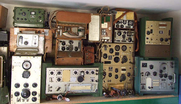
Military Wireless Museum
The Japanese Section

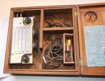
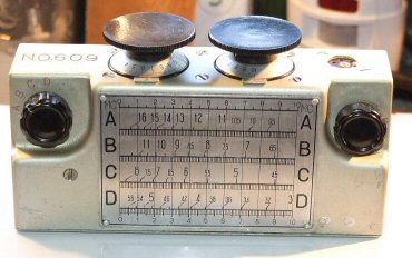
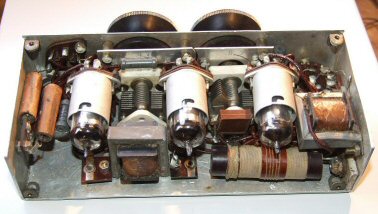
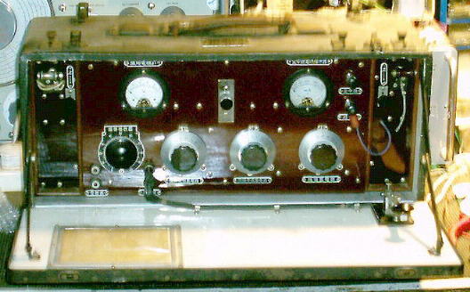
"Mukinanu". The receiver is considered to be a regenerative 0-V-2 consisting of three battery tubes B-03 manufactured by Shinagawa Electric, and its use frame-type antenna. The model and use of this portable shortwave receiver is unknown, but it is said that this one was manufactured by the Army Technical Research Institute for special agents. By the frequency chart on the receiver, this receiver operates 3-16MHz in 4 bands.
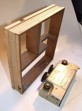
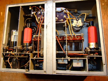
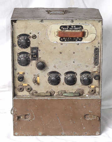
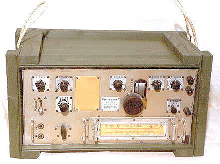
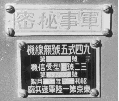
1942 Army Weather receiver, still more info to find out.
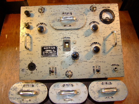
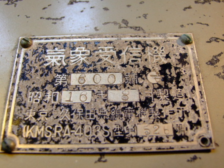
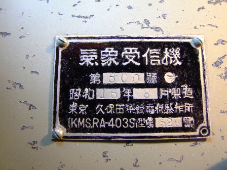
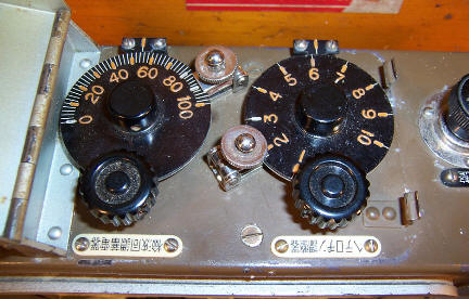
The data plate after a little TLC.
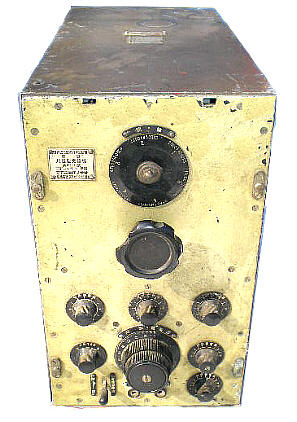
First line ; Vehicle-Mounted Receiver (says “mounted on a vehicle,” an older Army term used before standardisation.)
Second line : No. 500 (Serial number)
Third line: Manufactured August, Showa 10 (1935) A very early pre-war production date.
Forth line : Tokyo Kubota Wireless Electric Works A known 1930s radio manufacturer supplying the Army.
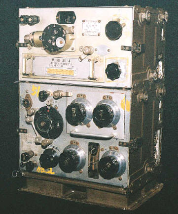
Recent addition: Wireless Radio A No135 Model 1, 1945. As received and under restoration.
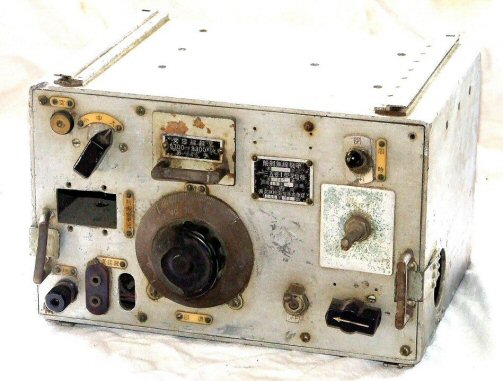
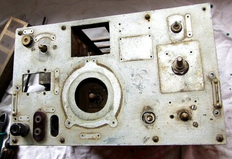
And after a little work.......................
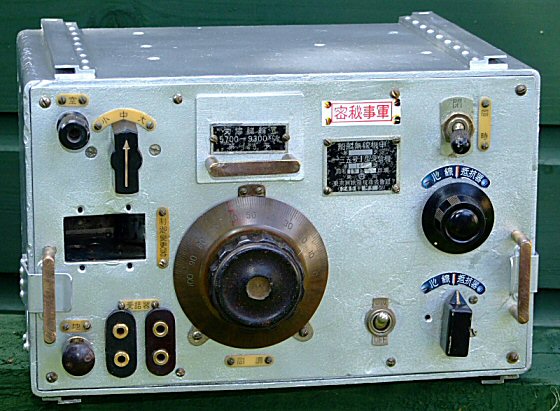
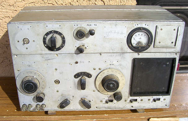
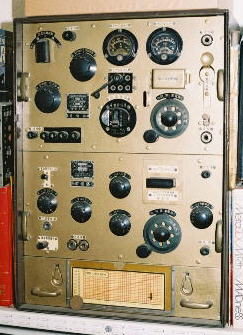
Army special Reception set but obviously a copy of Nationals NC100 range. 1.5 to 20MHz in 5 bands, has a Xtal filter, mains psu, 9 valves.
Set dated Jan 1942 I believe.
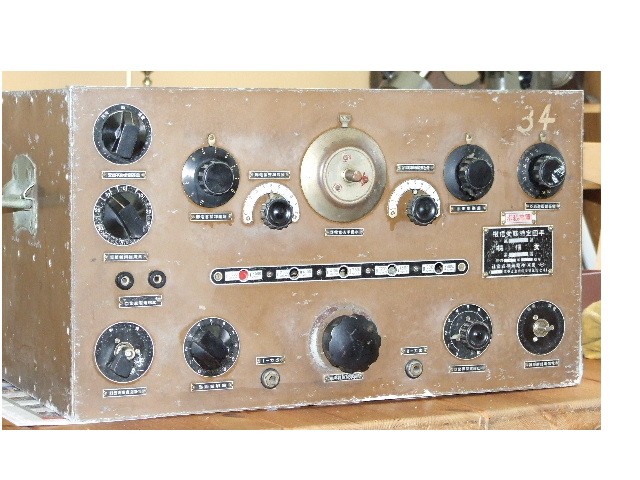
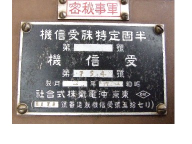
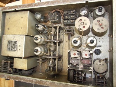
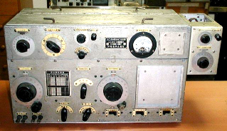
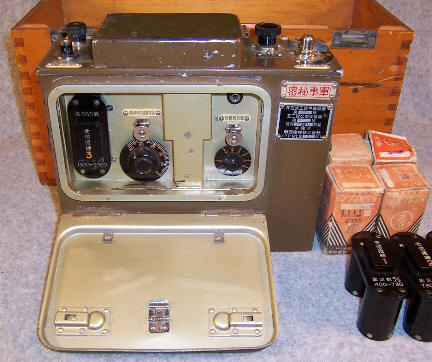
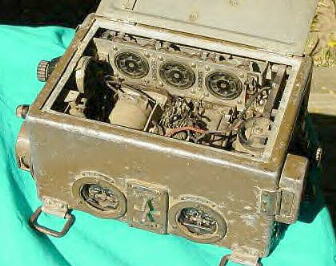
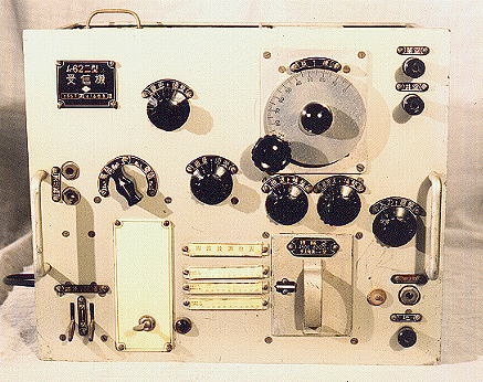
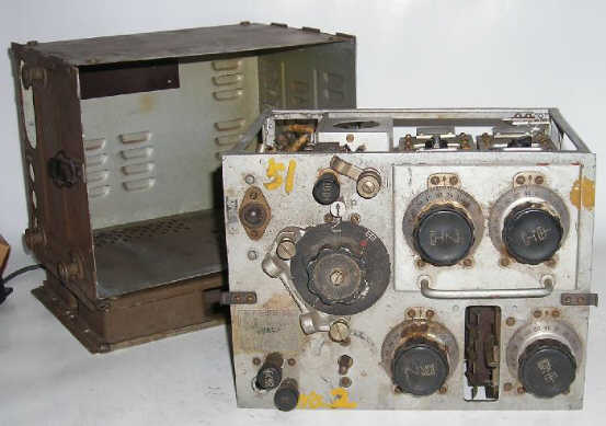
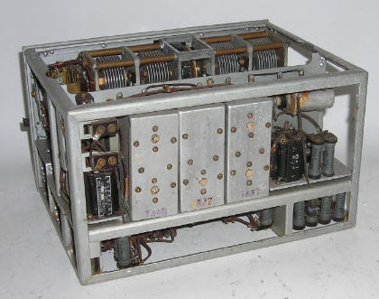
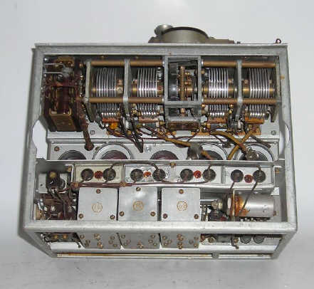
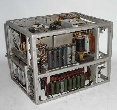
(Oki Electronic Company) semi-fixed special receiver, No.57 receiver.
Planning started Showa 10nen (1935) in April and after one year, this receiver was manufactured. Type A of model 57 Receiver
Receiving frequency: 1500 to 20,000KC
Super Heterodyne, High Freq amp, Frequency convert OSC, Intermediate Freq amp 2 stage-DET-AF amp, with AVR.
Tubes:  UZ78 Valve x 4pcs.   UZ77 x 1pc,  UZ41 x 1pc,  Ut6A7,  Ut6B7,  KX80
DC needs 200V,8V.  supply AC 100or 200V ±15% 50or60c/s
Gain below 12MC 135db, Gain over 12MC 130db. Selectivity:Attenuation 30db and over at±5kc
This receiver used with 2kw HF transmitter.
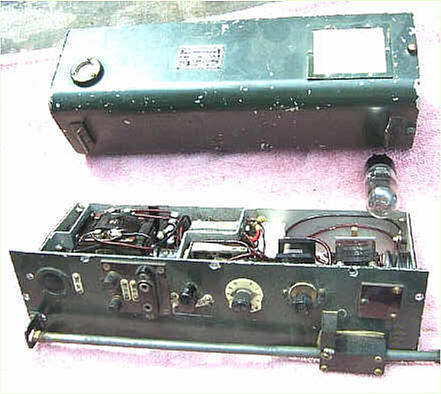
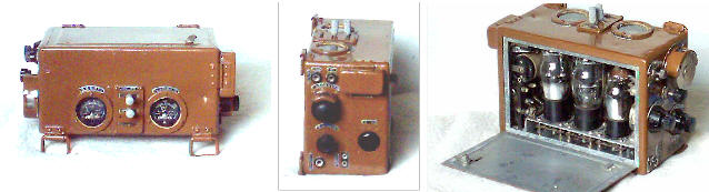
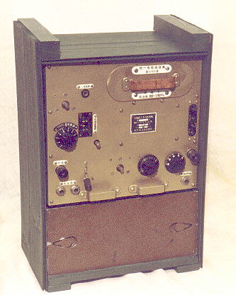
Another Recent addition. Model 92 Mk 4 Special receiver.
Just arrived, this receiver is in need of a bit of love and restoiration will begin shortly.
Left the set as it arrived, and right, what it should look like once restored.
Type HT
Left: A rather special Japanese set, a Walkie Talkie resembling the US BC-611 somewhat but operating on higher frequencies.
Machine translation from Japanese: It is thought the thing was produced for naval and land use. Function is equal to 97 type handy radiotelephones, there are 2 types which equip the thing and the troop type terminal for antenna connection which equip the rod antenna of 120cm. This equipment and material development at the beginning (1944 February) the microphone telephone receiver is equipped inside, it was the walky-talky telephone where also the electric battery for power source is built in. But after that, capacity of the small-sized high pressure electric battery (150v), it was modified to have the microphone telephone receiver and the power source electric battery outside the radio which have reduced problem in supply and operativity etc of the equipment and material. simple wireless radio of superregeneration detection and self-excitation dispatch system of single valve. Communication range: 500m frequency: 23,000-31,000kHz radio wave type: A2 (irregularity telegraph) and A3 (telephone) transmission output: 0.5W use vacuum tube: 31MC 1. TX: Self-oscillation, plate modulation, receiver: Superregeneration detection, it is low frequency 1 step power source: Dry cell battery 4V and 150V antenna: 120cm rod antenna.
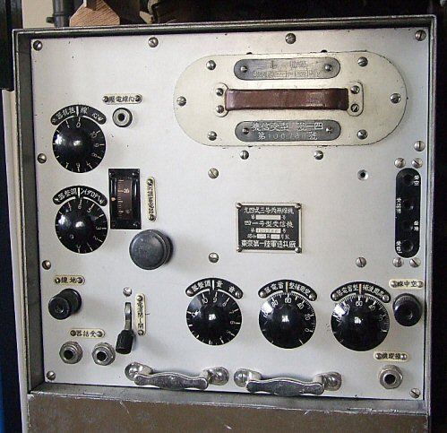
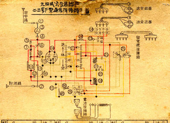
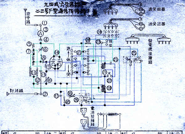
Type 94-3
RIGHT: A 94 Type 3 Special Receiver, in quite good condition so hope to have it working soon.
Type 53C
Type 53C receiver, in its box, with coil packs and spare tubes. 0.4 to 5.754 MC using 5 plug in coils., CW, MCW, and voice, using miniature tubes., weight given as 11 lb. including batteries. Made by the Tokyo Instrument Co., a very compact regenerative receiver.
Type 66
Recent addition. Type 66 HF transceiver. 3 Valve hf set, apparently quite rare. I have started restoration, this involves basically a paint touch up, reglazing of the two meters and finding a couple of knobs.
The set is a battery powered radio covering 2.5 to 4.5 MC. It is capable of AM and CW. It uses three UZ 109C double triodes. It is housed in a metal case and the batteries are contained in a box in a leather pack. Weight is 8.1 lbs. and the battery box and pack are listed as 2.1 lbs. The set is 11 x 4 1/2 x 7 1/2 inch metal cased. Basically waterproof it but not tropicalized. Tuning dials are graduated 0 - 100 requiring reference charts for tuning . Transmitter controls are on one side with a socket for the xtal, the mic and an external Morse key. There is an internal key, mounted on the side. Receiver controls are on the opposite side along with power socket and headset socket. Mounted on the top are two meters and three lever switches for transmit, receive and mode selection. The tubes are easily accessed fro the front door but other parts would need a major strip down. d the power cable. After a bit of a clean up and tlc...
Type TM HANDY
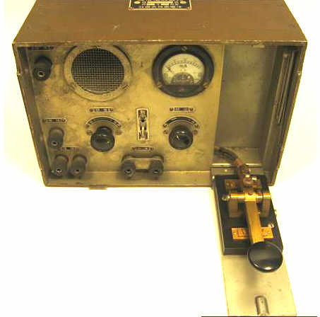
Another recent addition: TM Handy Set, Japanese Navy. 2 valve, 4-12 Mhx, 2.5W CW... more later
Machine translation from Japanese: This equipment is the portable type simple telegraph of conveyance possible trunk type, TM system shortly with the mobile radio telegraph, is the typical communication equipment and material of the naval marines. Because it is handy, in addition to overland fighting, the vessels and the land and between the steam launches it is in the midst of anchoring in the harbor, in addition it made the auxiliary wireless radio of the small-sized warships and was used at the naval various parts. Use: Portable equipment and material communication range for short-range communication: 5Km frequency: 4,500-11,000kHz radio wave type: A1 (telegraph) transmission output: 1W use vacuum tube: UY-27 x 2 transmission: The self-excitation dispatch, reception with UY-27 parallel use: Autodyne system, detection UY-27, it is low frequency expansion UY-27. power source: Dry cell battery & storage battery or AC power supply antenna: At the dry cell battery & the storage battery in case of use vacuum tube UX112A x2 is equipped. Furthermore, as for the notice equipment and material the dial and the like differs from the former TM telegraph in later type.
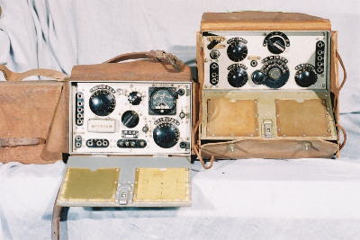
Type 94-2 MK2
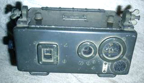
LEFT: Receiver Type 94 -2 Mk 2. Ground to Air communication. After a clean it looks really good, even better when I found it still worked. Just one broken wire on the bfo switch. A previous owner had removed the rotary ht generator and built a mains (115v) psu in its place. I have now removed this and replaced it with a 6v inverter supply, the set is now operational again.
Type 94-3
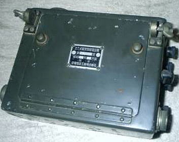
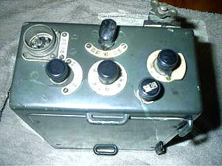
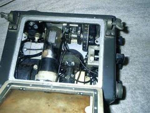
RIGHT: The mule carried field set, Model 94 Mk 3, houses a single valve transmitter and a s/het receiver. The batteries for rx htr and ht and tx htr are carried in the compartment at the base, the tx ht was provided by a handcranked generator.
Machine translation from Japanese: 94 types 3 shell wireless radio, upper transmitter, sublevel main receiver and electric battery box for lower position receiver It is the principal equipment of army division Communication Station.for short range it was used. Communication range: 80Km frequency: Transmission 400-5,700kHz and reception 350-6,000kHz. radio wave type: A1 (telegraph) transmission output: 10W. equipment summary transmitter: Crystal or self-oscillation 510B receiver: Superheterodyne system, the high frequency 1 step and the intermediate frequency 1 step, playback detection, (UF134-UZ135-UF134-UF109A-UZ133D) transmission power source: Hand turnable generator, reception power source: Dry cell battery antenna: Opposite L type (pillar high 7m and horizontal length 20m), earthwire: 20Mtr.
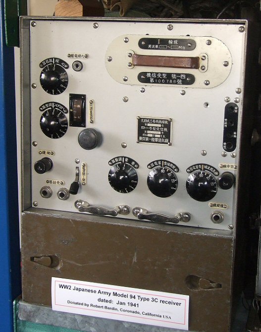
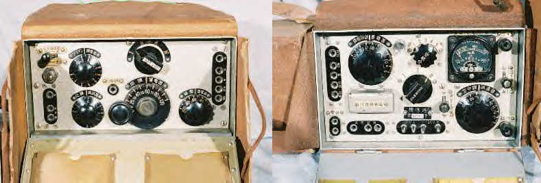
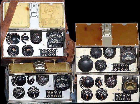
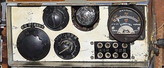
Type 94 3C RX
Another 94 3C receiver received recently. Pics as it arrived, awaiting cleaning and restoring.
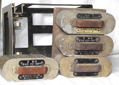
Another rececent arrival, very kindly donated to the museum
Type 94 MK5
This super little combo is a receiver transmitter, Model 94 Mk 5, hf, qrp, and still going strong..
Receiver on the left, transmitter on the right
Type 94 MK6
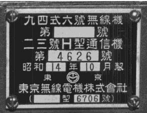
A very small VHF set, Model 94 Mk 6, man pack, single valve rx/tx ..This is my collection of 94-6 sets, the usually seen 3 band sets and below, a better picture of the rarer single band set, an early production version.
The data on my sets: Single band, no s/n but 196 stamped in base, meter dated 1937 and transformer dated 1937.
3 band sets:  s/n  4626,  dated 1939
              s/n 10081,  dated 1941
              s/n 102554, dated 1943
The circuit of the 94-6, in 2 shades to help with faded lines:
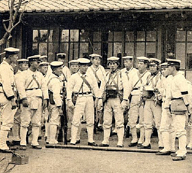
Side view of the VHF set, showing the small Morse key built ito the side of the case................................................... Set in training.
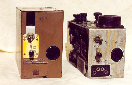
Type 97
Model 97 Easy to use Wireless Telephone, Product No 181-2 Navy Logo, Made in June 1943, Sendai ( a city in Japan) by Nichiden Radio Manufacturing Company Ltd.
Machine translation from Japanese: This is a field radio for the Naval Marines. Army 94 type 6, it is the same function as this radio, but it confronts waterproofing, where there is somewhat of a consideration. Communication range: 1Km frequency: 23-31 MHz tuning, radio wave type: A2, A3. transmission output: 0.5W equipment summary: uses vacuum tube: 31MC 1. Transmitter: Self-oscillation, plate modulation. Receiver: Super-regenerative detection. Dry cell battery and hand turnable generator. Antenna: L type, vertical section 140cm and horizontal section 65cm.
TOBI Type 99-2
Army Aircraft set, Type 99 MK II, Tobi type 2. Army Model 99 "Tobi" Mark 2 Radio Set for mid-range aircraft, Type 97 heavy bomber, Type 100 command recon and others Frequency: Tx 2,200-10,000 kHz, Reception 1,500-10,000 kHz, though this set has an 8 to 15MHz coil pack.: A1, A3. Tx power: 35W (A1), 10W (A2, A3) Tx: Crystal oscillator, Amplifier 807A, Anode modulation 807A Receiver: Superheterodyne system, 6F7x5 tubes. Power Supply: Rotary transformer input 24V) Antenna: fixed inverted L, 40m trailing wire.

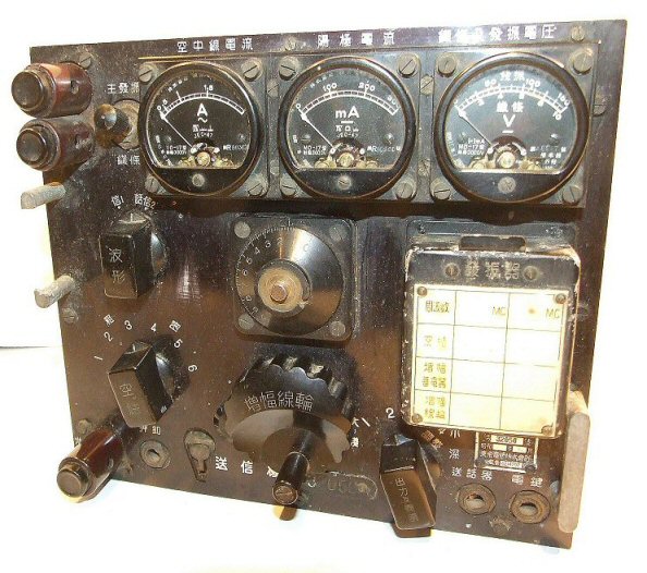
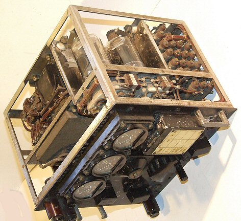
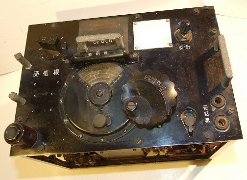

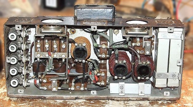


plate 1 Type 99 Aircraft Radio No. 2 This is the standard designation for an Imperial Japanese Army Air Force radio set introduced in 1939
Sanyo Electric Co., Ltd. (The wartime predecessor of today’s SANYO)
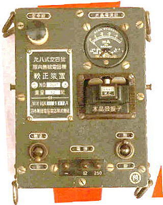
plate 2 Type 2 Aircraft Radio (Part of the same family as the Type 99 “Hi?2” airborne sets.)
No. (Serial number field — blank). DC Transformer / DC Voltage Converter
This identifies the specific component: the power?supply unit for the radio.
Manufactured May, Showa 18 (1943) Sany? Electric Co., Ltd.
plate 3 Input side....High voltage output side....Low voltage output side
Type 99-3
Now, another Army Aircraft set Model 99 "Tobi" Mark 3 Radio Set. Obviously from a crash wreck. So, do I restore or leave as is. Thats the question. ed: Have decided to restore, pics later.
Now after some restoration work the set is starting to look a little better.
Amazingly, I found another, complete set.
Machine translation from Japanese: It was the radiophone equipment for the single seat fighter plane of the army,it was loaded onto most Army's single-seat fighter, and was installed in most fighters such as Falcon, Falcon, and Hien. Communication range: 100Km (air- ground) frequency: Transmission 2,500-6,700kHz and reception 1,500-6,700kHz radio wave type: A2, A3. transmission output: 10W (A2 and A3). Transmitter: Crystal oscillation UY807A, plate modulation UY807A. Receiver: Superheterodyne system (MC804Ax5), the high frequency 1 stage, intermediate frequency 2 stages, low frequency 2 stages Power supply: DC transformer (24V) antenna: Fixed inverted L type.
Click here for more details of the restoration of the Zero set
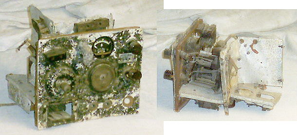
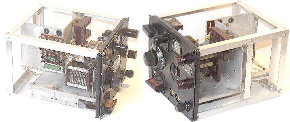
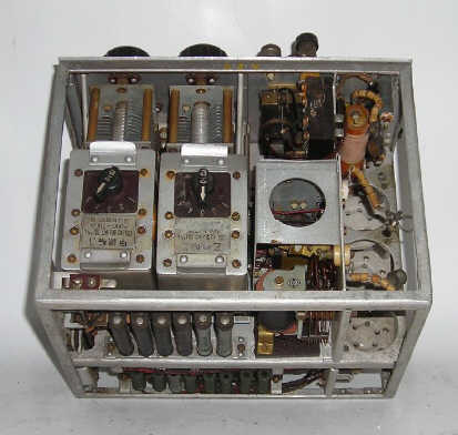
Type TOBI Mk V
Tobi Aircraft receiver and transmitter Mk5.
 |
 |
 |
 |
|
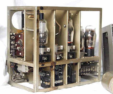
internal Fig 1 |
internal Fig 2 |
uinternal Fig 3 |
internal Fig 4 |
The Tobi pair, cleaned up and nearly ready to go..
Type CHI MK1
LEFT: The Japanese version of the HRO, using a similar system of plug in coil units and external power supply. The set uses 9 valves in a single conversion role but with an added feature of the user being able to select between two IF ranges, depending upon the band in use, by using plug in IFT units.
Type 41 D
RIGHT: Another receiver, Mark 41 Type D receiver part of the Model 94 Mk 3C station, awaiting restoration, plug in coil pack again..
Machine tranlation from Japanese: It was the equipment for anti-aircraft telephonic communication, it was used with army division Communication Station and artillery troops etc. Communication range: 50Km frequency: Transmission 400-5,700kHz and reception 300-5,700kHz radio wave type: A1 (telegraph), A3 (telephone) transmission output: 5W equipment summary: Transmitter: Crystal or main oscillation UY47B, power amplification UX202A and audio expansion UY47B, plate modulation UX202A. Receiver: Superheterodyne system, the high frequency 1 stage and the intermediate frequency 1 stage, af and detection, (UF134-UZ135-UF134-UF111A-UF109A-UY133A) transmission power source: Hand turnable generator reception power source: Dry cell battery antenna: Opposite L type (pillar high 5m and horizontal length 20m), earthwire: 20Mtr.
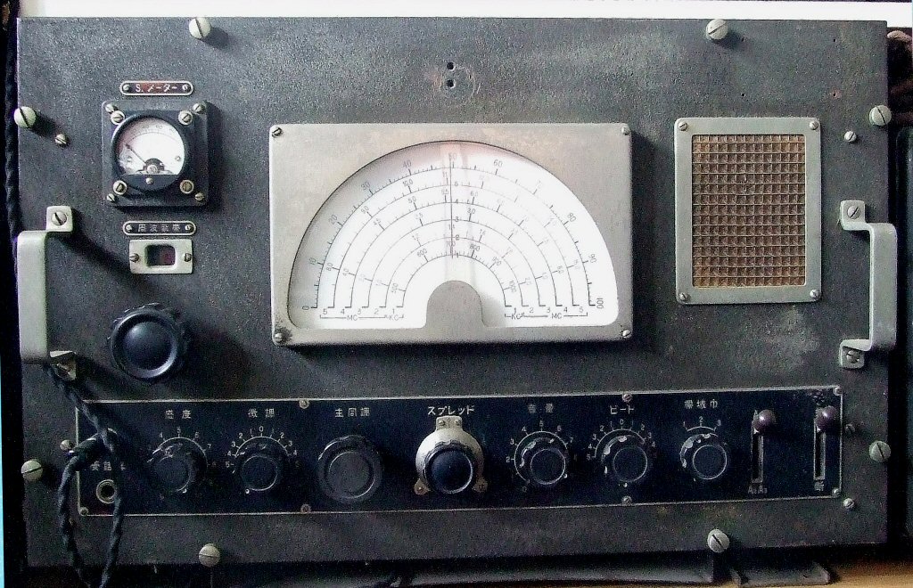
Type RH-901
Model RH-901, was used by the National Safety Forces, the predecessor of the Self-Defense Forces. 500kHz to 15MHz.
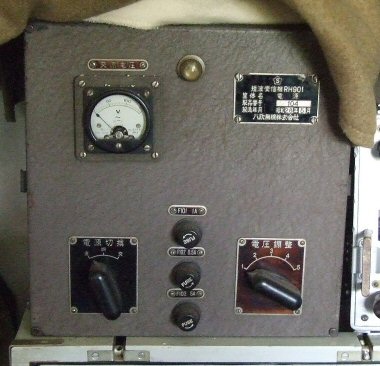
The power supply unit for the receiver
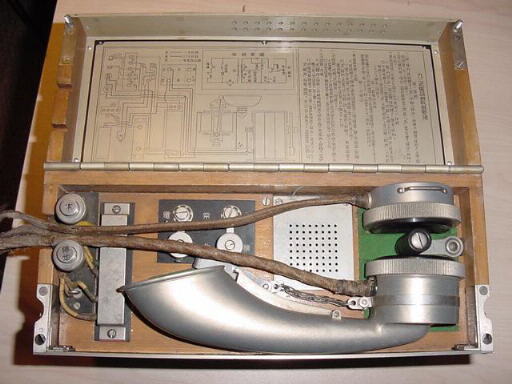
Recent item in the collection, Japanese Field telephone, dated Feb 1943
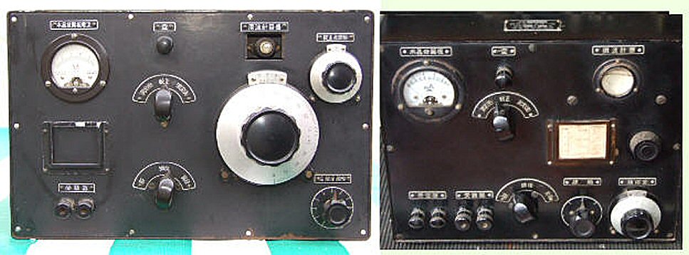
A pair of Frequency Meters now, interesting, both sold as receivers but when received it was obviouse what they were. That's the trouble with buying off plan I guess.
From Takashi Doi: "Ben- san, You have two Navy frequency maters. One is Model-2 Mark-1Type-2 Radar(Mark 12 Radar) Frequency Meter, range from 90 to 185MHz. Mark 12 was mobile type early warning radar which mainly used at front line. Other one is Model-99 shortwave Frequency Meter range from 2,400 to 12,000KHz. This one was mainly used on ship."
A small Naval test set, crystal calibrator with modulated output. The xtal inserts behind the central door and is powered from an
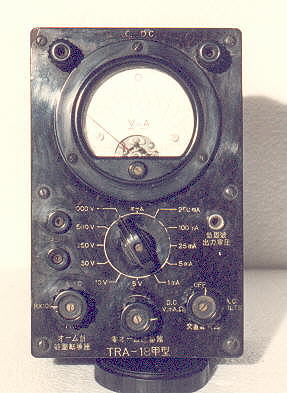
external supply (battery ?). I believe the unit was used for Naval Aircraft radio alignment. Also, a nice little Japanese Test Meter, still working.
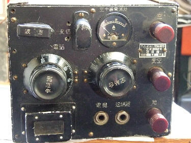
TELEGRAPH SETS. Model 95 set which can be used in conjunction with Model 92 telephone. The set has a built in key arrangement. It probably is used by lower units for administrative traffic.
 |
 |
|
Fig 1 |
internal |
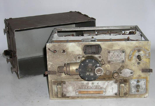
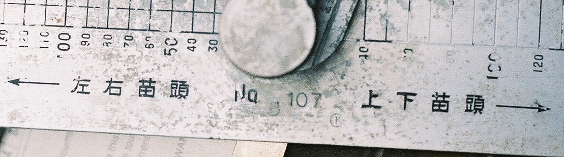
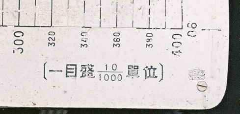
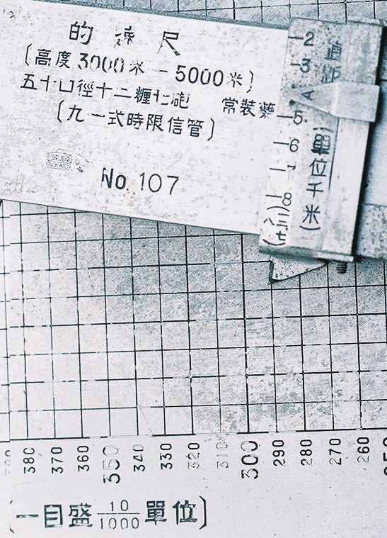
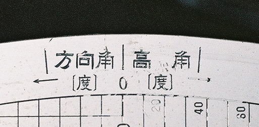
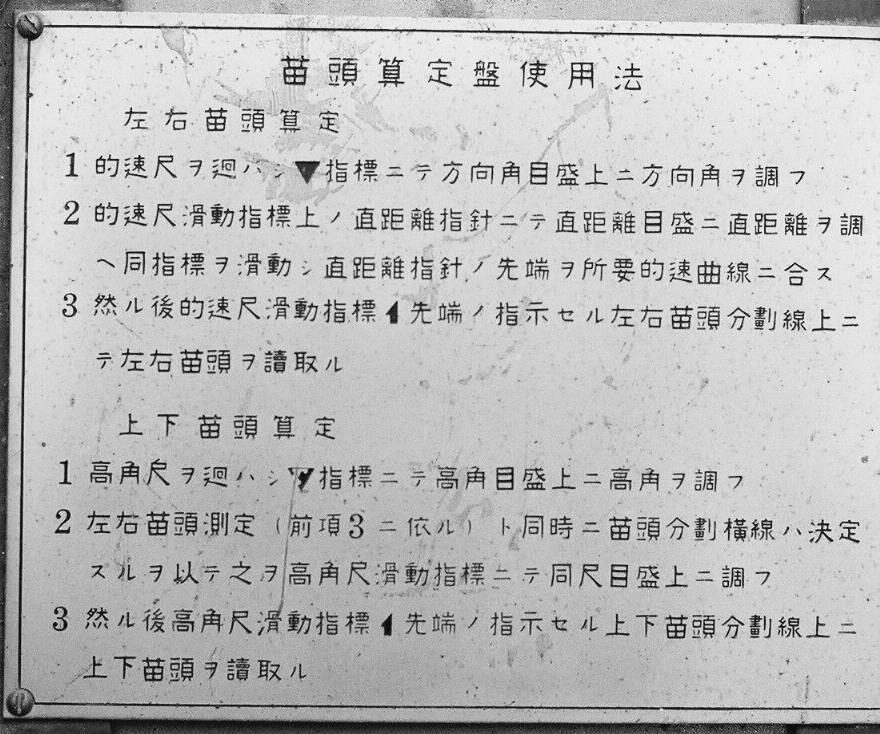
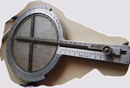
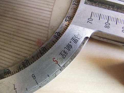
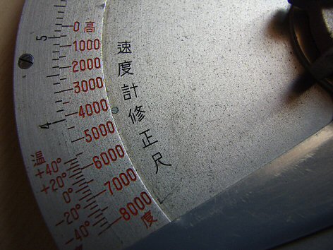
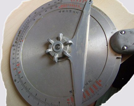
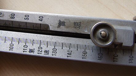
An interesting item found at the back of a junk shop in Cornwall. Apparently, it's an Army Gunnery calculator, Plotting fall of shot and the like. The characters are to do with degrees, angles etc. So, if anyone knows where I can get a Japanese artillery piece?
( Click on small images for a larger version)

 |
 |
 |
 |
Another calculator, Air Navigation or bomb drop maybe?
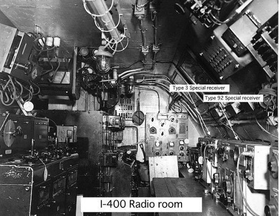
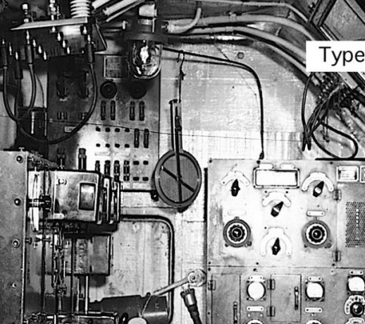
Interestig find, photo of I-400 Japanese submarine, item in centre of radio room picture.
Domo Arigato, Konichiwa...............
Send an e-mail to: Ben Nock, G4BXD
(If link does not work on your PC then send email to: [email protected] )
********* Pictures by G4BXD are G4BXD copyright ********