Military Wireless Museum
Welcome to the
 section !
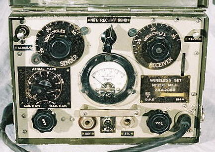
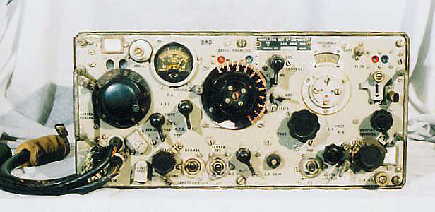
WS-208 MkII
LEFT: One of the Australian sets here is the WS-208. Very similar to the 68 set, covers 2.5 to 3.5 MHz with maybe 500mW output CW only.The 208 transmitter/receiver was produced by Radio Corporation of Australia (ASTOR) in Melbourne in 1942. The set has 6 valves, 4 for the receiver and 2 for the sender, i.f. of 455 kHz. The frequency range indicates the set was designed for tropical jungle operation, A similar set, the 108 Mark 3, provides AM operation over the same frequency range while the earlier 108 Marks 1 and 2 with their higher frequency ranges, proved unsuitable for tropical jungle conditions, because of signal absorption. The set was supplied with an external battery box, l.5v heater supply and a 90 & -105v battery block for H.T. supply. The L.T. current on tx is 200ma and 250ma on rx. H.T. drain is l8ma on tx and 8.5ma on rx.
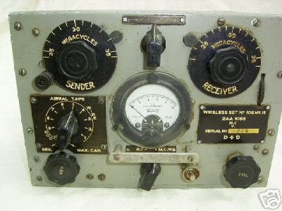
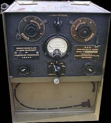

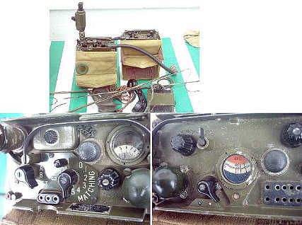
WS-108 MK II and III
Top right: is the WS-108 Mk III, The pa input was 0.5 to 0.6 watts, depending on frequency and aerial. It can operate on AM and MCW on 2.5 MHz to 3.5 MHz.Bottom: the WS108 Mk II, the higher frequency version, similar in role and use to the UK WS18 I guess.
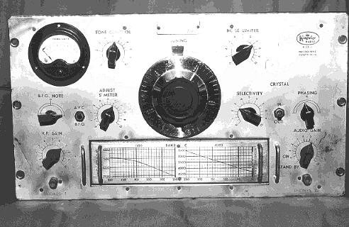
WS-101
An Australian made WS No101, working and operational on 80 mtrs, after a slight tweak, hi. This was a Antipodean copy of the British Wireless Set No 1, an example of which is in the Royal Signals Museum at Blandford.
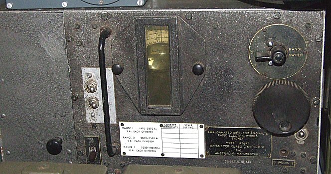
CLASS C W/M
RIGHT: This is the Wavemeter Class C used with the 101, its used to check frequency of both rx and tx, the compartment on the left holds the batteries, or in this example, a mains psu.
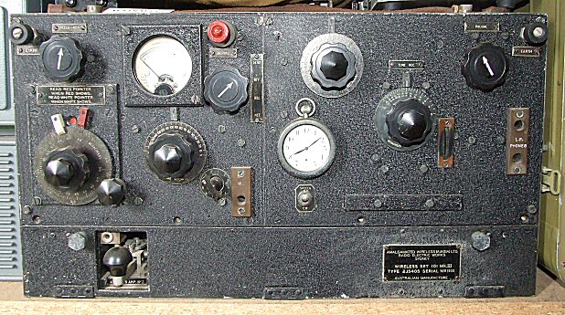
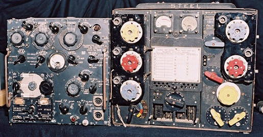
ws-128
Good front panel, case will need a dab of paint. On the list of things to do.
WS-122 and A510
The Australian version of the WS22, very compact wiring inside.
The A510 manpack set, used by infantry, hf, am/cw, very compact little set. Shown here in its transit box with all acc's including hand generator.

AR-7
The Australian AR7 receiver, very similar to the American HRO, same type of dial and plug in coil packs. Used by the RAAF. This one is in need of restoration, wires have been cut, IFT's are hanging off and it has 60 years of grime inside it. Hopefully though, after hours of work, it should be a working set.
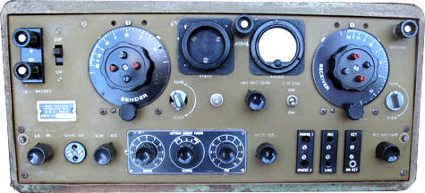
AR-8 AT-5
The Australian AR8 receiver, very similar to the British R1116A set, twin tuners, common IF stages. DF function on this set as well. Used in the RAAF planes, in conjunction with the AT5 transmitter.
It consists of the AR8 receiver, the AT5 transmitter, Aerial Tuning Unit for the AT5, and a 12, 24, or 240V power supply. There is also a junction box and a remote control unit. The AR8 receiver consists of two independently tuneable front ends alongside one another, one for HF, the other for MF. There is a facility for a loop connection to allow direction finding bearings to be made. The receiver is a dual conversion superheterodyne type. The transmitter consists of two seperate master oscillators, one for MF and one for HF. On MF a VFO is used. HF allows the use of either the VFO or a crystal oscillator.
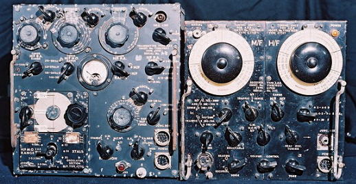
RIGHT: The AT5 tx compared to the T1154 set.
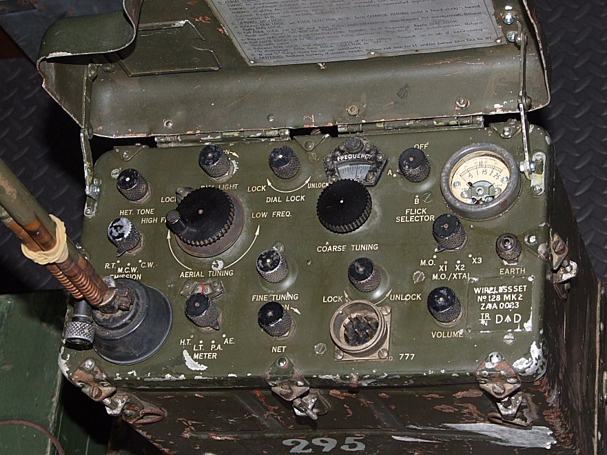
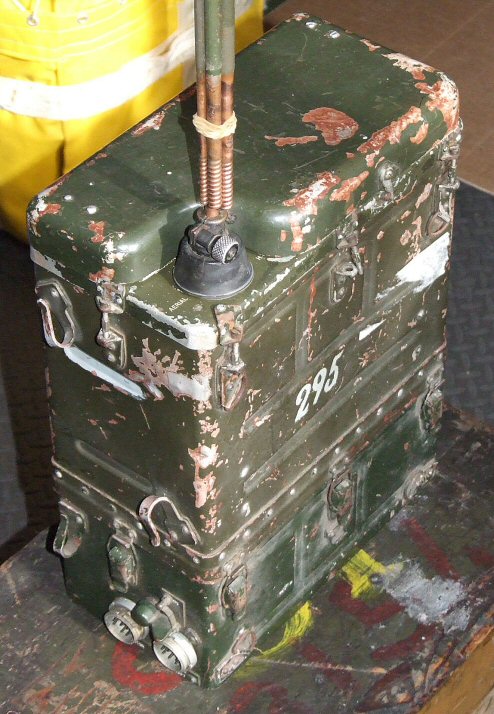
ZC1 MK I
Not quite Australian but in the same area, hi. The New Zealand version of the WS19 set, the ZC1 Mk 1.
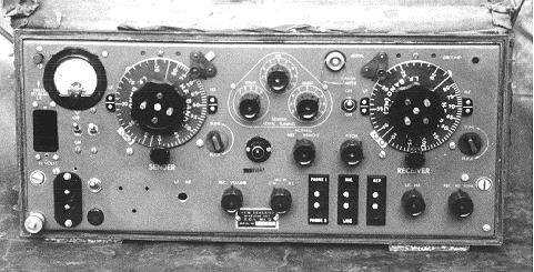
ZC1 MK II
and right the ZC1 Mk II. Very heavy, low powered but a nice set.
The ZC1 M2 Wireless Set was designed to replace the ZC1 M1 providing additional facilities particularly in connection with WT. The set was partly tropicalised and was for use on the ground or in a vehicle. With Amplifier RF No ZA1 MK 2 it provided longer range and air support communications. The Range will vary with frequency and the type of aerial used. Typical ground wave ranges, RT 15 to 20 miles, CW 20 to 25 miles. The sender and receiver are both designed to operate between 8 mc/s and 2 mc/s in two bands. HF Band 8.0 to 4.0 mc/s and LF Band 4.0 to 2.0 mc/s. The output power varies between 1.6 and 2.0 watts depending on frequency and aerial. A BFO provides resolution of CW signals. Power Supply for the set was from two 6 volt 85 Ah batteries in series providing 12 volts. rx (Sender valves off) 2.8 amps, rx (sender valves on) 3.8 amps, tx CW 4.4 amps and tx RT or MCW 4.9 amps.
More to come, page still under construction

Send an e-mail to: Ben Nock, G4BXD
(If link does not work on your PC then send email to: [email protected] )
********* Pictures by G4BXD are G4BXD copyright ********