 Here are some pictures of the transverter:
28/144MHz Transverter and Station Controller
After many years of using my FT736R to both drive transverters and provide 144MHz talkback, I decided in late 2004 to have a separate driver for the microwaves to make talkback easier to manage. I could have taken the simple option of something like an FT290/FT817, but after some research decided that the Elecraft K2 would be a good basis for the prime mover. The K2 has good RF specs and provides very good support for transverters - the K60XV option adds extra jacks for low-level transverter output and also provides access to address lines for controlling which transverter is used. Up to 6 transverter bands can be supported, in addition for each transverter band the display can be set up to show the output frequency (without the MSD for frequencies above 1GHz), and can have the maximum drive level individually set and also adjust the display to take account of up to +/- 10kHz LO offset. More details of the Elecraft K2 can be found at:
The K2 covers all bands up to 28MHz, so the next question was how to transvert this to the 144MHz IF used for most microwave transverters. Elecraft produce one themselves, but it was unclear if the control of the XV144 would also permit automatic band changes for attached higher band transverters, an additional control box may have been needed to decode the K2 transverter addressing. I decided to go for a homebrew solution that would be customised for my station. The transverter spec required that it supported the following features:
28-29MHz IF, 144-145 MHz RF
"Good" dynamic range
Switching for routing 28MHz IF to 70MHz and 1296MHz transverters
Switching to route the 144MHz RF to transverters, antenna, or PA
Control circuits to operate T/R relays on each band
Sequencing to prevent RF getting into receiver front ends
5W maximum output
Simple control using K2 bandswitching
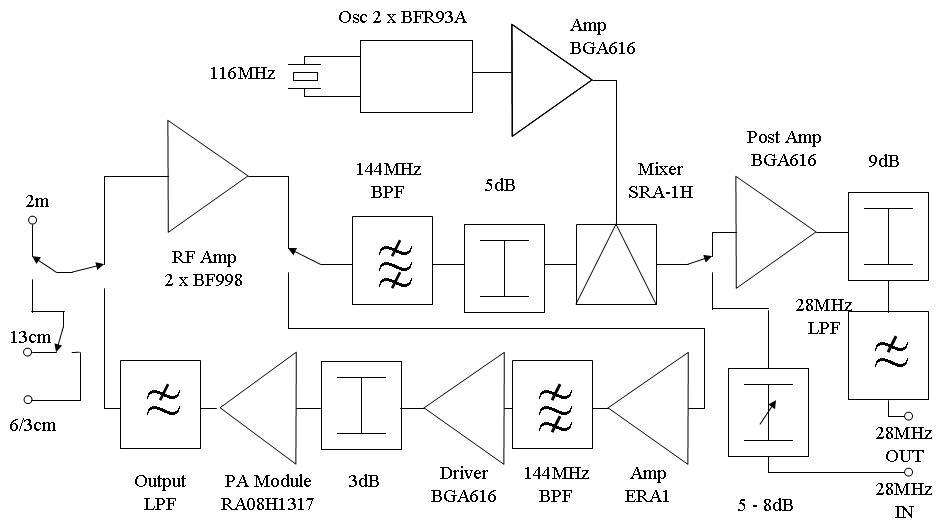
The design is a hybrid of several high performance transverter designs. The receiver RF stage and local oscillator design come from S53WW, the filtering is based on the Suffolk transverter by G4DDK, and other aspects are my own design. The Receiver front end uses 2 x BF998 devices in parallel to increase dynamic range. The state of the art S53WW Javornik transverter uses 4 devices to give optimum IP3 performance, 2 devices are enough here due to limitations further up the receive chain. The output of the RF stage goes through a 3 stage filter to remove the image and other out of band signals, and then via a 5dB pad to an SRA-1H high level mixer. The 5dB pad means that the mixer sees a minimum of 10dB return loss on its input port, and is chosen for a good compromise of NF and dynamic range. The SRA-1H is fed with +19dBm of LO power from a BGA616 SiGe MMIC. These devices are very cheap (about 1 Euro each) but provide excellent input and output matching and high dynamic range. The LO itself is a variant of the well known Butler oscillator and is a copy of the Javornik design. A 40 degree Murata crystal heater is used to help reduce drift. Another BGA616 is used as a post amplifier for the mixer. The input return loss of the BGA616 is more than 20dB over a wide frequency span, so the mixer is correctly terminated without needing to use a diplexer to separate out the wanted product. The gain available is excessive so a 10dB pad is used in the ouput circuit, prior to a 2 stage low pass filter that reduces out of band signals in the 28MHz output. A lower gain device which did not need an output attenuator would be a better choice to maximise dynamic range.
On transmit the 0dBm signal from the K2 is passed via simple variable T attenuator to the SRA-1H mixer and back through the 5dB pad and 3 stage filter. The resulting signal is at a level of -20dBm. This is amplified to about -8dBm in an ERA-1 MMIC and then fed to a second 3 stage filter to further suppress out of band signals, then into another BGA616 which is the driver for the PA module. A 3dB pad prevents the PA module input power rating being exceeded. The PA module is a Mitsubishi MOSFET device, the RA08H1317M, rated at 8W on a 12V supply. The module is biassed on by a 3.3V regulated supply which is enabled on transmit. Relays are used for all the signal switching - NAIS TQ2 types at 28MHz (similar to those used extensively in the K2) and G5Y UHF types for 144MHz switching. The control circuitry is based on a PIC 16F873A device programmed to decode the band select and T/R inputs from the K2 and operate the appropriate relays and MOSFET switches in the transverter. The PIC is interfaced to the relays and the external control lines via a pair of ULN2803 darlington driver chips. The PIC also drives 6 LEDS, one per band, which show green on RX and turn red on transmit. All of the I/O lines are committed, but there is plenty of spare program space in the 873A - the cheaper 16F870 device would have been perfectly OK for this application. I used a ready made PIC development board from Forest Electronic Developments. This was my first PIC project, so the code underwent several iterations and is currently at version 11. The chip was programmed using a Velleman PIC programmer built from a kit bought in Maplin Electronics.
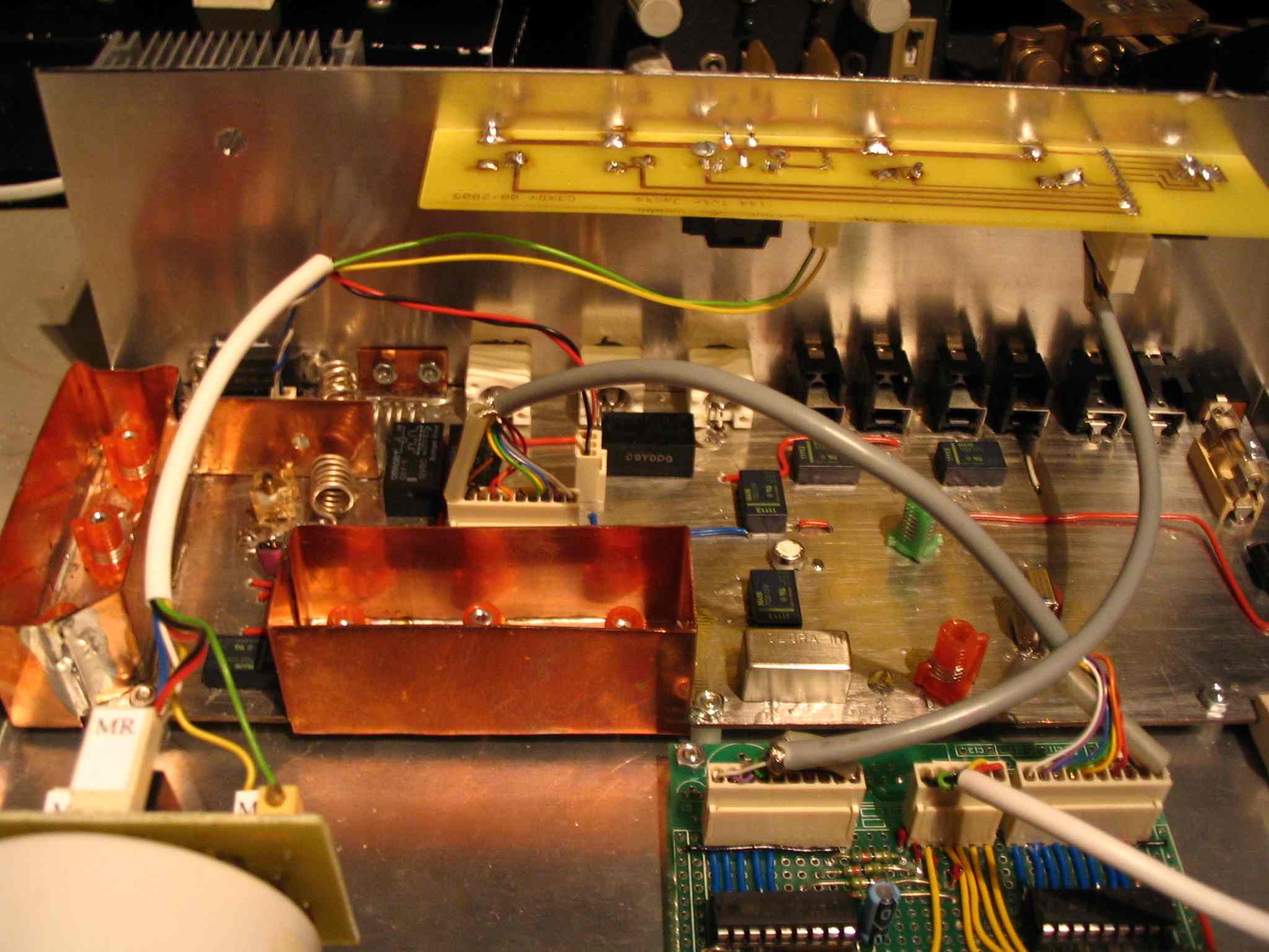
Most of the electronics is underneath the board, using SMD components (mainly 0805 size devices), so it appears well spread out. The space requirements for the input and output connectors determined the overall size and shape of the PCB used.
Initial measurements with an HP9870A NF meter and HP346A low ENR source show the NF to be 1.45dB and gain 24.5dB.
Here is a block diagram of the transverter:
Here are some pictures of the transverter: