New Masthead System
In early 2015 I decided it was time to renew the cables on my tower and make some other changes I had been planning. The existing cables were 24 years old and showing their age.
The upgrade consisted of the following work:
1. Fit a new higher capacity cable for the rotator. The existing one used 0.5mm2 conductors and this was replaced with 0.75mm2
2. Replace the existing control cables. Several cables had been added over the years to increase the number of control lines available, these are now consolidated into one 12 core0.5mm2 cable
3. Replace existing UR43 cables with lower loss modern versions. I used LMR195 equivalent for these for the IF feeds for 3.4GHz (432MHz IF) and 5.7/10GHz (144MHz IF). The 3.4GHz feeder also transports a 10MHz GPSDO output to the masthead to lock the transverter local oscillators.
4. Replace H100 and W103 cables with LMR400 equivalent. This reduced the cable weight a lot, as the LMR400 type is aluminium cored (copper plated) and aluminium foil shielded. Originally the H100 carried the 432MHz and 1.3GHz preamp outputs back to the receive converters, with the W103 split between 70 or 144MHz transmit, 432MHz transmit, and 2320MHz preamp output. One feeder now carries the receive preamp outputs for 432/1296/2320MHz and the other is just for either 144 or 70MHz depending on which antenna is installed.
5. Replace the LDF4 going up the tower with a more robust feeder system. Frequent failures in the LDF4 have been experienced, and a new, lower loss, and more rugged system was put in place using a mix of LDF5 and LDF4 with better support where the cable bends.
6. Replace the existing 60cm offset fed dish for 9/6/3cm, as this was starting to rust. Also move the 9cm feed to the 80cm dish forming a dual band feed for 13/9cm.
7. Add elevation control for the two dishes.
8. Upgrade the 432MHz and 1296MHz preamp to include an extra relay for switching the TX feeder between the two bands.
9. Prepare for future installation of a 24GHz system.
Most of the upgrades were completed in September 2015. The modifications to the 432/1296 preamp needed a complete rebuild of the preamp box, as the waterproof seal on the box had failed (after 30+ years) and there was insufficient space for the extra relay, this was completed in December 2015. This step also involved making changes to the way the 432MHz preamp was powered, with modifications needed to the 432MHz transverter and the 432MHz SSPA, and a new 3 way coax switch in the shack to switch the SSPA outputs from 432, 1296 and 2320MHz to the LDF5 feeder.
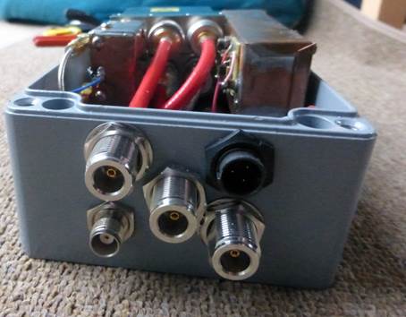
The DC cables now terminate in a waterproof plastic box on the head unit about 50cm down from the top bearing. This contains an interconnect strip for the 12 way control cable and power distribution for 17V DC supplied to the masthead. There are connections for 5 plugs on the top of the box and one below, plus four cable entry glands. All the coax cables except the LDF5 terminate in a waterproof diecast box, with four incoming cables below and five bulkhead sockets on the top of the box which terminate the cables for the turning loop. Inside the box is a diplexer that combines the outputs from the 2320MHz preamp and the 432/1296 preamps (there is already a diplexer in the 1296MHz preamp which combines the 432MHz signal). See picture below:
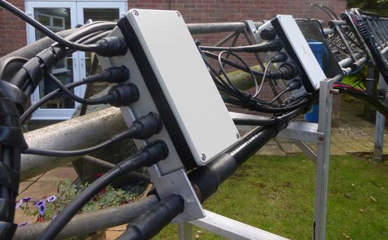
The main transmit feeder now comprises a 6.5m length of
LDF5-50 from the shack up to the top of the bottom section of the tower, where
this transitions to 4.5m of LDF4 with a cable carrier that prevents the bend
radius becoming too small, see picture:
At the top of the photo you can see the 7/16 connector pair used to join the LDF4 to the LDF5, all enclosed in glue filled heatshrink sleeving. The cable carrier is made from aluminium plate and angle and will allow +/- 90 degree bends in the cable as the mast is raised or lowered, whilst maintaining a safe bend radius. The cable form is enclosed in a long length of spiral cable wrap to keep the bundle together whilst allowing the cables to move relative to each other as they bend.
Beyond the 4.5m of LDF4-50 there is another 7/16 connector pair and then a 4.5m length of LDF5-50 up to the top mounting bracket. This cable is also securely clipped to the head unit. The turning loop is FSJ4-50 (not FSJ4-50B – the B version doesn’t use a stranded copper core so is less good where a lot of bending occurs) which is terminated on the 2320Mhz preamp box and is routed via a Narda relay either to the 2320MHz antenna relay or back out again over a 1.5m length of LDF4-50 to the 432/1296MHz preamp box.
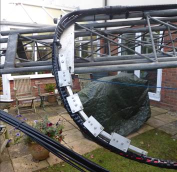
The new elevation system is shown in the picture below. The cross arm is thick wall 30mm diameter aluminium tube running in PVC sleeve bearings, with further pvc collars as thrust bearings. A 6 inch throw satellite jack rotates the tube over about 60 degrees travel, and a pot driven by a lever provides position feedback, see photo below.
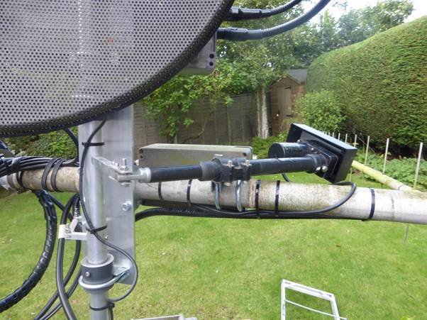
The transverters for 9cm and 6/3cm are now mounted on the rear of the dishes, see the photo below:
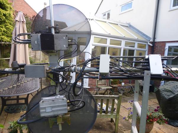
The spare cross arm space towards the top of the picture is available for future installation of a 24GHz system. The box on the stub mast between the two transverters is the 2320MHz preamp.
The picture below shows the feedhorn
for 5.7/10GHz with a preamp for 10GHz mounted in a small waterproof housing
behind it. The top feeder is FHJ2-50 on 10GHz, that
below the feed support arm is LDF4-50 for 5.7GHz. The horn has a cover made
from Kapton sheet to try and keep spiders out!
The dish feed for 3.4GHz and 2.3GHz consists of a dual dipole and reflector feed for 2.3GHz, which is a simplified version of the feed used before, but with a single central support using 0.25 inch semi rigid cable (RG401). The 9cm feed consists of a ring feed which passes around the semi rigid coax for the 2.3GHz feed. This feed is located very close to the groundplane and has little effect on 2.3GHz performance. With careful adjustment over 20dB return loss was achieved on 2.3GHz and 17dB on 3.4GHz, with about 15dB of isolation between the antennas at 3.4GHz (more at 2.3GHz). The relay configurations used for antenna changeover ensures the 2.3GHz antenna is not connected to the 2.3GHz preamp when transmitting on 3.4GHz, and vice versa. The feed can just be seen in the photo below, inside the polycarbonate radome made from old 2L drinks bottle:

The photo below shows the feeder arrangement with the thicker semi-rigid cable used on 2.3GHz and the UT141/RG402 on 3.4GHz.

The new preamp for 432 and 1296MHz is shown in the picture below. Most of the internal coax cable is RG401 (.25 inch) hand formable cable. The 432MHz preamp is the copper box at the top, and comprises a tuned input line with a NE32184 device with a simple resistive drain load. The output from this preamp is combined with the signal from the 1.3GHz preamp in a diplexer which forms part of the 1.3GHz preamp at the bottom. This uses an ATF54143 HEMT in a design by YU1AW in the first stage, followed by a MGA53543 high dynamic range MMIC. There are three changeover relays stacked up, with 432MHz antenna changeover at the bottom of the pile, the transmit switch between 432 and 1296MHz in the middle, and the 1296MHz antenna changeover at the top.
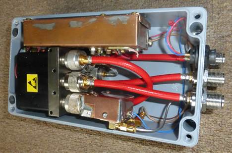
The three N types below are (R-L) 1.3GHz antenna, transmit feeder, and 432MHz antenna. The combined preamp outputs are on the TNC socket, and there is a 3 way Switchcraft connector for control/power