144MHz SSPA with LDMOS protection circuit
My old valve PA (2 x 4CX350A) for 2m finally gave up the ghost in late 2016, the main blower motor failed, and other parts were showing their age (it was about 45 years old!). It was time for the station to finally become fully solid state.
Although I don’t use 2m often (too much man-made noise) I still need the capability from time to time for microwave talkback or getting the attention of DX stations to move to higher bands. There were several options, the first decision was whether to buy a ready-made PA or build my own. Having decided that ready to go amplifiers were rather expensive, the question was what design to build. Having looked around it seems there are several designs based on the F1JRD LDMOS amplifier described in DUBUS 2010/4. Although 1kW + output capability is overkill, the easy availability of parts from W6PQL for this design influenced my decision. After a bit of analysis of the datasheet for the BLF188XR device I came to the conclusion that it might be beneficial to run the amplifier on less than 48V to obtain better efficiency at the UK limit of 400W, so I designed the power circuit so that the amplifier can be run on any supply from 28V to 50V. A MOSFET series regulator drops the incoming supply to 28V for powering the main changeover relay and this is further regulated to provide 12V for bias and control circuits.
LDMOS Protector
G4SWX pointed out that the most likely failure mode for
LDMOS PA devices is due to overdrive causing gate breakdown. Several popular
rigs can generate a big power spike at the start of transmission due to poor
ALC design. Although my driver is not capable of enough output power to cause
this type of failure, I decided it would be prudent to include overdrive
protection.
Gaetan ON4KHG has published a design for a PIN diode
protection circuit which looked promising. In looking to modify it to use all
SMD parts, I realised that some improvements were possible. This led to a
design which uses three PIN diodes to provide a protection circuit which will
still work with no DC power applied to the amplifier, and which offers better
impedance matching in both on and off states.
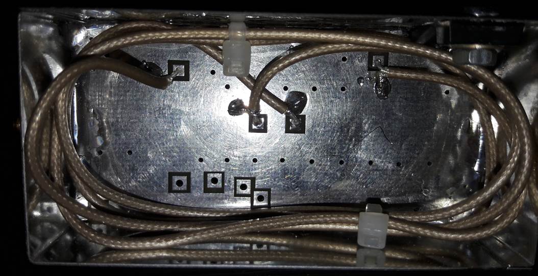
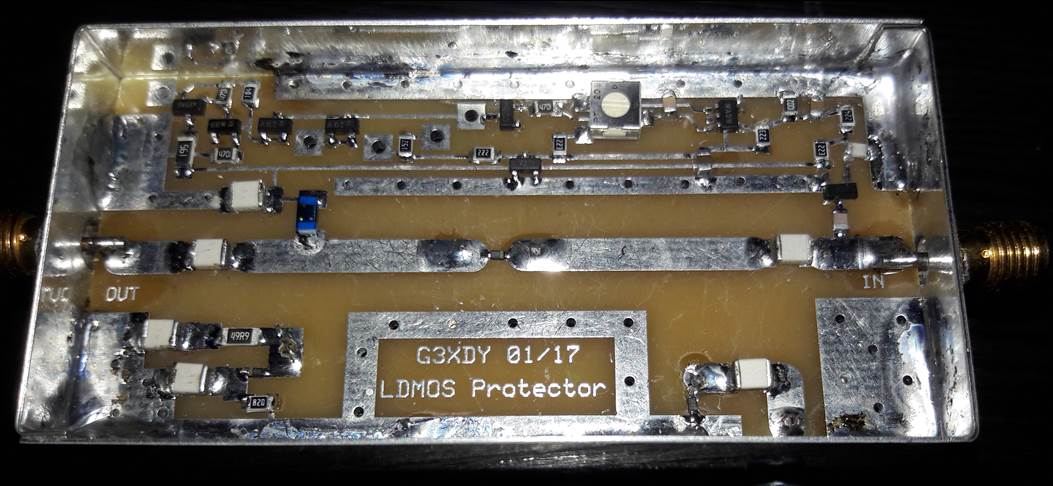
The switch has a series diode which connects the PA input to the driver when biased on, and two shunt diodes. In the “on” state the shunt diodes conduct with a forward current of 10mA and short out 50 ohm loads on the end of quarter wave lines attached to the input and output ports of the protector. The quarter wave lines transform the short circuit to high impedances shunting the 50 ohm line, so there is minimal mismatch and loss. In the “off” state all the diodes look like open circuits so there is no path between input and output, and both ports are terminated in 50 ohms at the end of each quarter wave line. If drive is applied in the off state, the RF power is dissipated in a 50 ohm power resistor, and the RF detector circuit generates a negative bias voltage to ensure the PIN diodes remain biased off.
The RF detector also feeds a comparator which switches if the incoming RF level exceeds a preset threshold, set by a pot. The comparator in turn triggers a silicon controlled rectifier which latches on. This switches off the forward bias on the PIN diodes, and also switches the PA bias off via the PA control board. An LED lamp on the front panel lights to show what has happened. Resetting the circuit can only be achieved by switching off the power to the amplifier.
The circuit shown has an “on” state through loss of 0.6dB, and offers at least 30dB of isolation in the “off” state, with return loss in excess of 20dB on all ports in both on and off states. The response time to an overload was measured as 28 microseconds. Any practical transceiver or transverter will have a longer rise time for the RF output so should be fine. The only situation where the circuit might not be fast enough is where a faulty relay circuit hot switches excessive RF into the PA input.
Several of these protectors have been built by others and seem to work satisfactorily. Availability of a kit or bare PCB is under consideration.
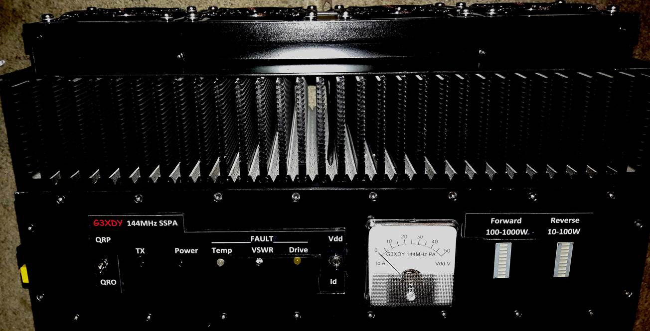
PA Cooling
I had a large aluminium heatsink available which made a good platform for building the PA. This heatsink is forced air cooled using 4 fans, normally only the inner pair directly over the amplifier pallet operate when the temperature rises far enough. The second pair provide additional cooling if a second temperature threshold is exceeded, but have not in practice operated yet. Running at 400W output on a 28V supply rail, the output coax cable gets warmer to the touch than the heatsink after 2 minutes of key down operation. There are also two small internal fans, one to cool the PA matching transformer lines and other components on the pallet, and the second one to cool the low pass filter so that the coils do not overheat. The LPF was carefully tuned to minimise the through loss at 144MHz and so reduce the power dissipated.
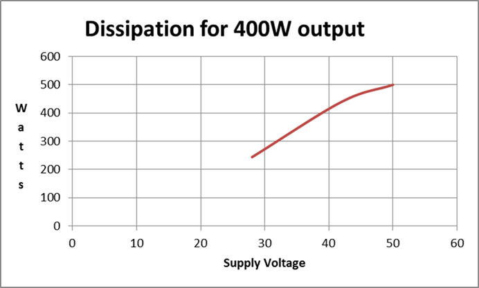
PA Efficiency
The power dissipated at 400W output on supply voltages of 28V, 42V and 48V is shown in the attached graph. It is clear that operation on the lower voltage has benefits when running 400W, and the LDMOS device will have an additional margin of safety against any load mismatch. The output power reaches 1kW with a 42V supply and about 3W of drive, and well over 1kW with a 48V supply. Now all I have to do is solve my local noise problems!


|
Bill of Materials for G3XDY LDMOS
Protector |
||||
|
Designation |
Value |
Secondary
Parameter |
Size |
Farnell
# |
|
C1 |
1.8pF |
200V |
0805 |
2672812 |
|
C2 |
100pF |
100V |
0805 |
499171 |
|
C3 |
1nF |
50V |
0805 |
9406212 |
|
C4 |
1nF |
100V |
1210 |
2332897 |
|
C5 |
1nF |
100V |
1210 |
2332897 |
|
C6 |
1nF |
100V |
1210 |
2332897 |
|
C7 |
4.7uF |
16V |
0805 |
2688537 |
|
C8 |
1nF |
100V |
1210 |
2332897 |
|
C9 |
1nF |
100V |
1210 |
2332897 |
|
C10 |
1nF |
100V |
1210 |
2332897 |
|
C11 |
10nF |
50V |
0805 |
2581081 |
|
D1} |
HSMS2802 |
|
SOT23 |
1056834 |
|
D2} |
|
|
|
|
|
D3 |
BAR88-02 |
|
SC-79 |
2443504 |
|
D4 |
BAS16 |
|
SOT23 |
9558659 |
|
D5 |
LED |
|
|
|
|
D6 |
BZX84C4V7 |
4.7V
350mW |
SOT23 |
1459051 |
|
D7 |
BAS16 |
|
SOT23 |
9558659 |
|
D8 |
BAR88-02 |
|
SC-79 |
2443504 |
|
D11 |
BAR88-02 |
|
SC-79 |
2443504 |
|
L1 |
470nH |
1206CS |
1206 |
2286952 |
|
Q1 |
BC817-25 |
NPN
|
SOT23 |
1081224 |
|
Q2 |
SI2309 |
MOS
P Ch |
SOT23 |
1779264 |
|
R1 |
50 |
30W |
TO220 |
2530958 |
|
R2 |
22k |
|
0805 |
|
|
R3 |
220k |
|
0805 |
|
|
R4 |
22k |
|
0805 |
|
|
R5 |
4.7k |
|
0805 |
|
|
R6 |
2.2k |
|
0805 |
|
|
R7 |
49.9 |
250mW |
1206 |
2057745 |
|
R8 |
82 |
|
0805 |
|
|
R9 |
100k |
|
0805 |
|
|
R10 |
4.7k |
|
0805 |
|
|
R11 |
10k |
|
0805 |
|
|
R12 |
4.7k |
|
0805 |
|
|
R13 |
1.5k |
|
0805 |
|
|
R14 |
560 |
250mW |
1206 |
|
|
R15 |
22k |
|
0805 |
|
|
RV1 |
10k |
250mW |
|
1520630 |
|
SK1 |
|
|
|
|
|
SK2 |
|
|
|
|
|
Th1 |
NYC0102 |
P0102BL |
SOT23 |
2533159/2396062 |
|
U1 |
MCP6561R |
|
SOT23-5 |
1834857 |