Construction of
“Sniffer”
1
Suitable for DF at 144mhz within 100mtrs of target
2
Battery operated
3
Could be made from the junk box parts
4
No special parts or PCB required
5 Cost approx £7.50 if parts be bought in
|
Construction of
“Sniffer” 1
Suitable for DF at 144mhz within 100mtrs of target 2
Battery operated 3
Could be made from the junk box parts 4
No special parts or PCB required 5 Cost approx £7.50 if parts be bought in
|
|
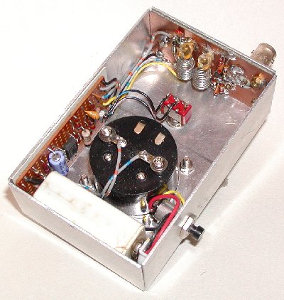
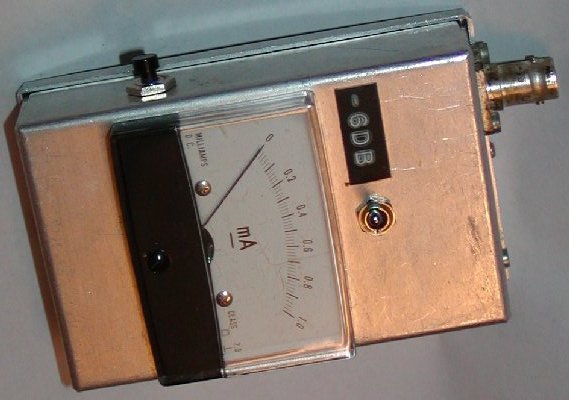
The unit
described is built in a stock aluminum box 102mm 67mm 36mm and powered by a PP3
9 volt battery that consumes less than ten milliamps when switched on so the battery
lasts almost forever. A BNC RF input socket is used to connect up the sense
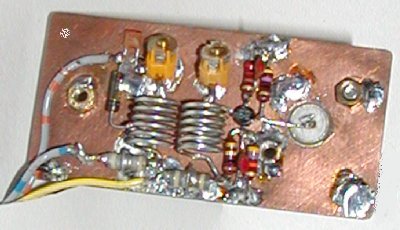
antenna, usually an HB9CV. The RF circuit is built dead bug style on PCB 63mm by
31mm, and the DC amplifier constructed on Vero board 23 by 12 holes point one
pitch.
|
Parts required 2 2-10pf trimmers RS 125-957
or 125-648 2 1000pf
feed through caps 2 1000pf
wire end caps 1 each 10uf
and 1uf 16 volt caps LM301 ic.
Germanium diode. 1N4148 diode. 3SK88 Mosfet. Resistors.
47ohm. 220ohm. 1k0 two off. 2k7. 8k2 two off. 12k. 15k. 100k. 2m2. Meter.
One milliamp FSD. 18 SWG wire for coils. 6 turns 6mm ID |
|
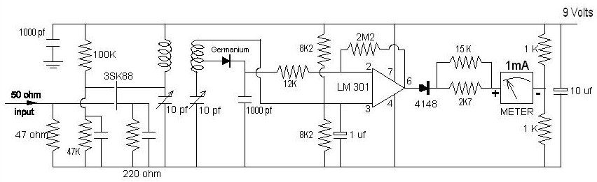
The RF part was the third tested. My first idea was to use a passive front end consisting of just the tuned coils to give some rejection to out of band signals driving the amplifier, but this was too insensitive unless very close to the target. My second used a preamp to drive the amplifier with an additional tuned circuit in the gate of the 3SK88, but this was too sensitive picking up RF from hi power PMR sites if they were close by. The final arrangement substituted the input tuning on the gate for a simple 47ohm resistor. This is what I have used for 2 meter DFs for the last few years.
One small mod I did a couple of years ago was to fit a switch to reduce the gain of the amplifier. In most cases this avoided the use of the external attenuator. It just connects a 1meg resistor in parallel with the 2m2 feedback resistor. Another idea would be to use say, a 100k in series with a 2m2 variable to adjust the gain. If I ever get around to building the Mk4 version I would build a stepped attenuator ahead of the 3SK88 into the same box and illuminate the meter or use an LED display to improve visual reading in low light levels.
Aligning
the RF coils can be done by directly coupling a signal generator to the sniffer
and adjusting the variable capacitors for maximum reading. If no generator is
available connect a sense antenna eg HB9CV and transmit low power from your
handy mid band say 145Mhz and adjust caps for maximum sensitivity. Keep the
reading on scale if necessary with your switched attenuator. Built as
described, the unit can produce a meter reading from 5 watts of RF from 100
meters away and yet is sensitive enough to read on low power, unmanned foxes of
50 milliwatts at about 5 meters distant. Some experienced foxes use higher power
to try and swamp receiving equipment. I found that using the 30db stepped
attenuator previously described ahead of this sniffer still kept the meter
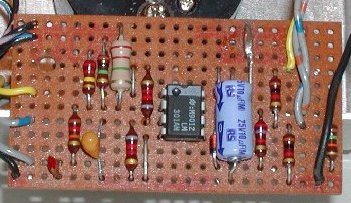
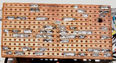
reading on the scale. The DC amplifier board is not critical except for the
value of the resistor in between the 1N4148 and the meter. Too large a value the
meter failed to reach FSD and with too small a value you bend the meter needle
round the end stop literally. 15k parallel with 2K7 produced a nice response up
to FSD when the circuit would current limit, avoiding damage to the meter. You
can see this 15k having been added at the edge of the board after straightening
my meter needle! Another addition at a later date was to add a compensation
capacitor of 47pf on the underside of the board between pin 1 and 8 of the
LM301. This is shown on data sheets for the device.
My
thanks to Colin G3RLA who took the photos.
Denis
G3UVR [email protected] Return
to construction and technical ideas menu