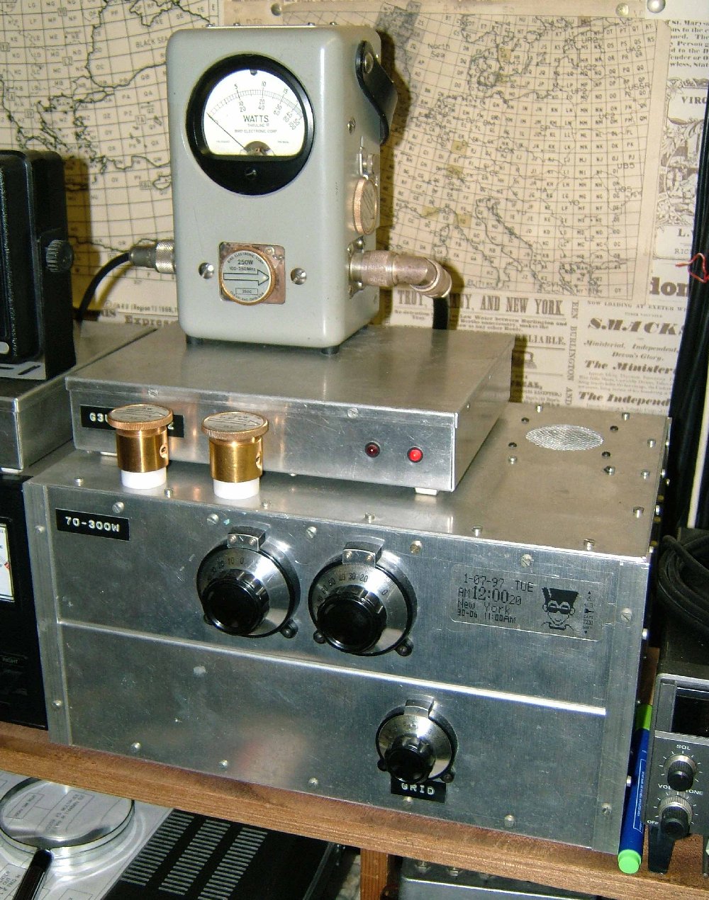
4CX250FG Amp and Transverter by G3UVR
Top cover removed

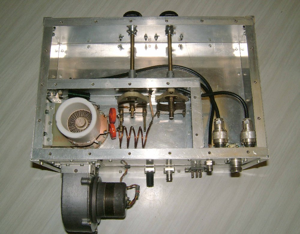
Bottom cover removed. Yes it is finished that's all there is !!
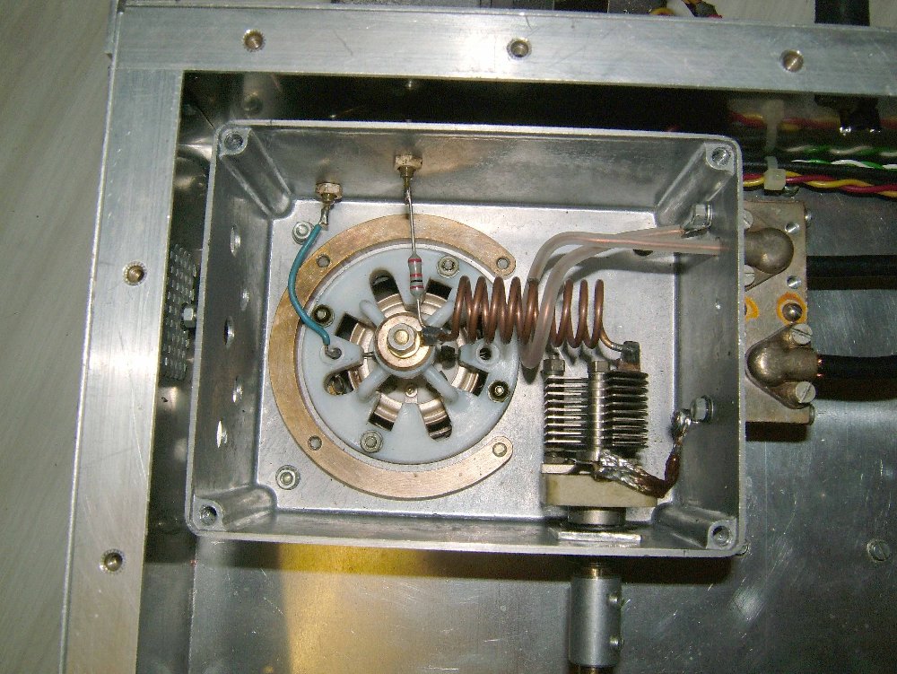
Grid compartment open. Not much in there either.
Circuit notes for the amplifier
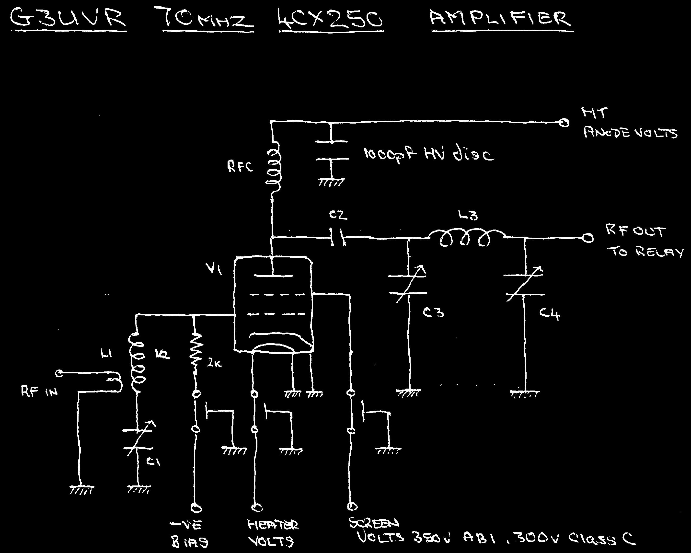
L1. 1 turn loop around L2 Made from RG58 inner core.
L2. 9 turns 1.8mm. 2mm spaced. 12mm internal diameter.
L3. 4 turns 2mm. 9.5mm spaced. 26mm internal diameter.
RFC. 23 turns 1mm. close wound. 9.5mm internal diameter.
C1. 50pf max variable air spaced.
C2. 2 off 1500pf high voltage 3kv +
C3. 26pf max. Wide air spaced. 3 fixed 2 moving vanes.
C4. 100pf max. air spaced. 6 fixed 5 moving vanes.
V1. 4CX250FG. 26.5 volt heater or standard 4CX250B. 6 volt heater type.
Bypass. 3 1000pf feed through capacitors for heaters, G1 bias and G2 screen volts.
I have been asked about the power supply for this amplifier. It was built from an article by G4AJW that was published in Radio Communication RADCOM October 1977. Yes its an old design but I have two still in use today. They power the 70mhz amplifier a 50mhz amp and a K2RIW on 432mhz.
Click here to view PDF of the PSU article
Click here for 4CX250FG Specification
Return to construction and technical ideas menu