The circuit was originally published in SPRAT
As Mike say's " It certainly won't take you very long to put one together to give it a try."
A large number of simple QRP transmitters use a VXO (Variable Crystal Oscillator)
The following are some of the circuits used:
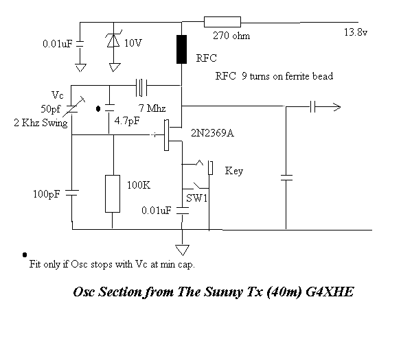
The oscillator section used in the Sunny Tx is of a Piece variety and gives a very stable signal even when keyed. With the circuit described VC1 will move it about 2 Khz, should a larger swing be required then an inductor of about 40 micro H can be put in series with the xtal and VC1. This has been tried with a variable inductor and moved the oscillator about 5 Khz.
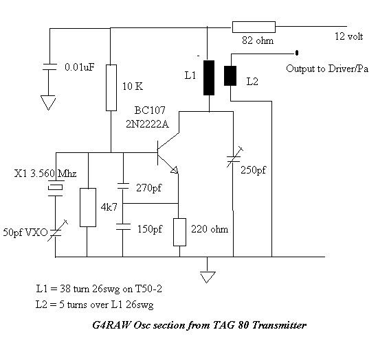
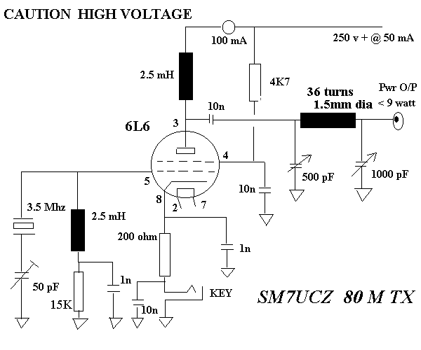
The next circuit is from a design by Johnny, SM7UCZ and uses a Valve, yep they are still used
The next circuit is commonly found in VHF equipment as either the Rx or Tx
Oscillator, it can be used of course as a suitable oscillator for use on 28Mhz
for e.g.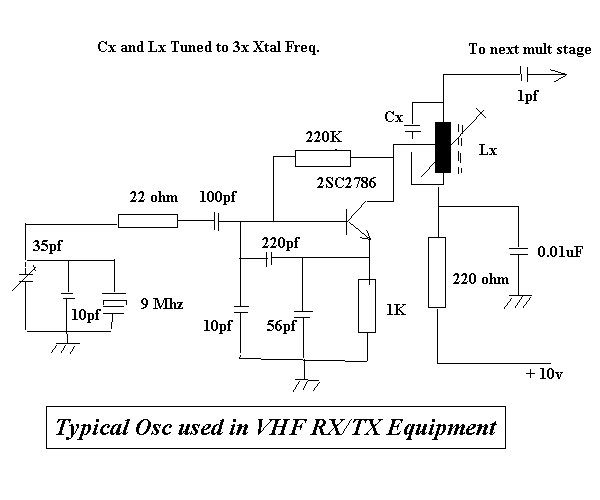
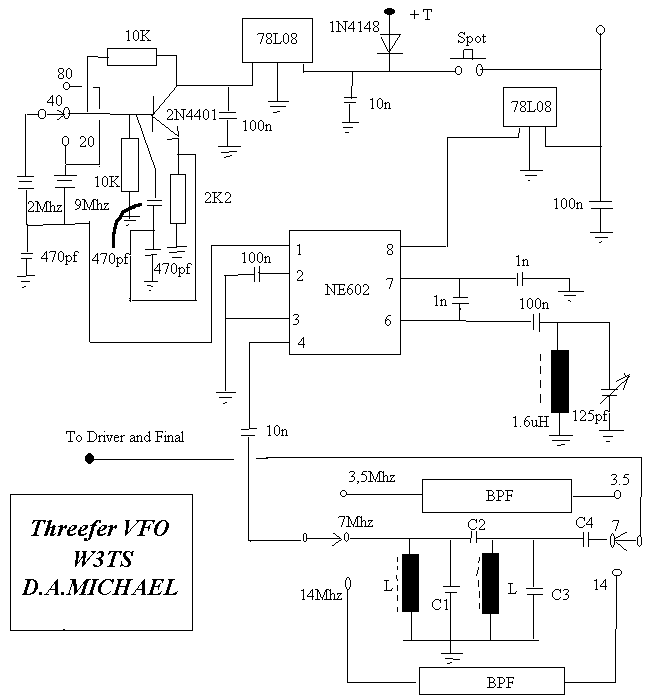
The Threefer VFO is an easy way to get a VFO controlled transmitter to run on three bands. The article and circuit appeared in SPRAT Issue 79
| BW | BAND | L | C1 | C2 | C3 | C4 | 10K Coil | OUTPUT |
| 0.5Mhz | 80m | 5uH | 350pf | 40pf | 200pf | 160pf | 19 turns | -12dBm |
| 0.5Mhz | 40m | 1.3uH | 390pf | 22pf | 300pf | 82pf | 10 turns | -13dBm |
| 0.9Mhz | 20m | 0.6uH | 210pf | 10pf | 160pf | 47pf | 7 turns | -14dBm |
This crystal mixer VFO uses the internal oscillator of an NE602 on 5 to 5.5Mhz to mix with 2 Xtals to produce a signal on three bands.
A 9Mhz crystal provides the 80 and 20m signal and a 2Mhz, the 40m signal. A Bandpass filter is added to the output for each band. The inductors for these filters are wound on TOKO 10K formers.
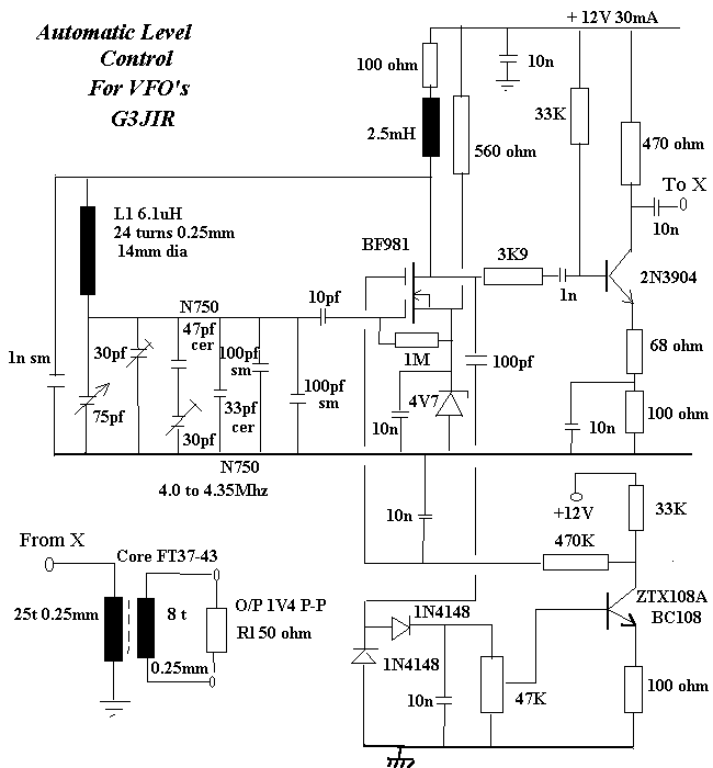
The VFO below shows a modified Vackar VFO with ALC control, operating between 4.0 to 4.35Mhz
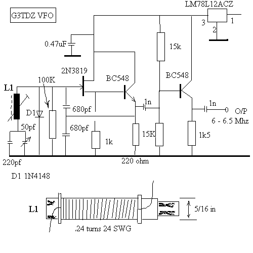
The next circuit shows the VFO used by G3TDZ in his Phasing Receiver.