I have now got to the point where I want a well constructed antenna that will perform well on 20m through to 10m for the space that I have. I will need to make a seperate antenna at a later date to get any reasonable efficiency on 80m and 40m should I wish to try these bands.
As I am not too bothered about 80m and 40m I was hoping I could make a loop small enough to pass through the access to the roof space. I used the RJELOOP and AA5TB calculators to get an idea of parameters and basing the diameter of the loop on the opening I realised that this would not be possible.
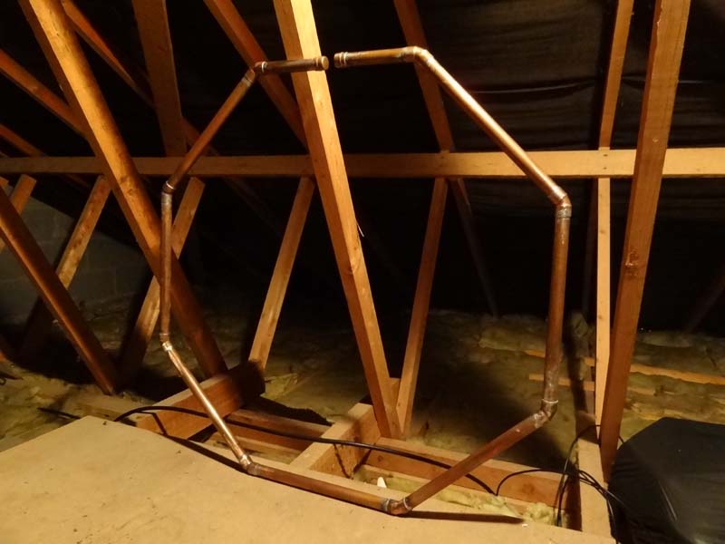
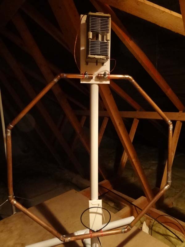
Not being an expert in pipe bending I have chosen an octagonal design that could be soldered up in the roof space but in hindsight I should have gone for a square design to reduce the number of resistive joints.
From reading various sources on the internet I knew I needed to keep the circumference of the loop between 10% and 20% of the operating wavelength so I calculated that each piece of my loop needed to be about 32cm.
This page is a "work in progress" to show what I am working with at the moment.
Using the RJELOOP1 calculator a comparison was made between octagonal loops having sides of 28, 30 and 32cm with overall widths ranging from 72cm to 82cm. Making the smaller loop would fit through the access hatch in to the roof space but I decided to make the larger loop and do the final assembly when through the hatch.
By constructing the larger loop 15m to 20m could potentially have as much as an additional 10% efficiency. The additional efficiency on 10m and 12m is in the region of 5%. Efficiency on 40m would increase from 6% to 8%. The capacitor required to tune the loop from 10m to 40m would be in the region of 12pF to 275pF or for 10m to 20m 12pF to 52pF.
I have read that a loop should be at least 10% of the wavelength of the bands you want to transmit on. The table below shows a few of the parameters calculated, notice the increase in efficiency and electrical length between 20m and 40m.
| Frequency (MHz) | 7.05 | 7.15 | 10.100 | 14.125 | 14.35 | 18.12 | 18.16 | 21.15 | 21.45 | 24.94 | 24.99 | 28.32 | 29.7 |
| Electrical Length (% at op freq lambda) | 0.06 | 0.061 | 0.085 | 0.121 | 0.122 | 0.155 | 0.155 | 0.18 | 0.183 | 0.213 | 0.213 | 0.242 | 0.253 |
| Transmission efficiency (% of pwr) | 8.28 | 8.66 | 23.48 | 50.68 | 52.06 | 71.07 | 71.23 | 80.85 | 81.6 | 88.26 | 88.33 | 92.14 | 93.27 |
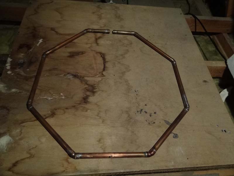
I managed to get off-cuts of 22mm copper pipe and purchased some 45 degree elbows and a couple of end caps. In the end I decided to cut the pipe to 32cm lengths, then soldered up in to a nice octagon leaving a 30mm gap at the top.
|
|
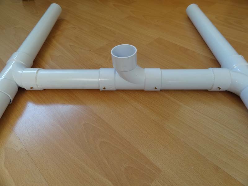
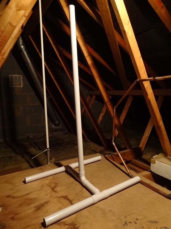
The support for the loop was made from 40mm PVC pipe. I could not find any T-connectors so used flow-in connectors instead.
 |
 |
|
|
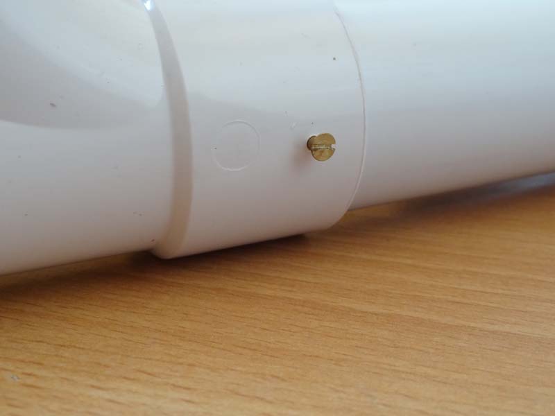
Brass securing screw used in addition to sealing compound
to stop coupling slipping.
|
In-flow or T-connectors can be used. |
Final support assembly. |
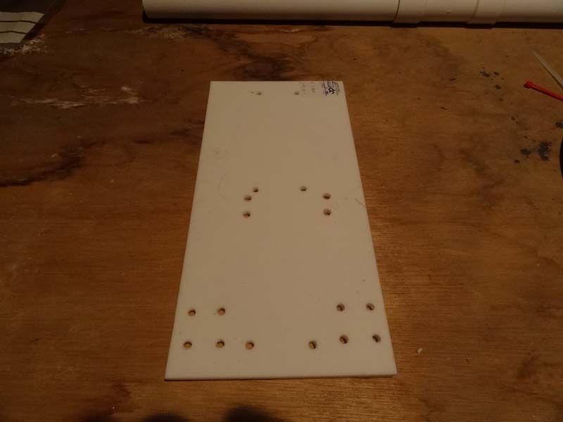
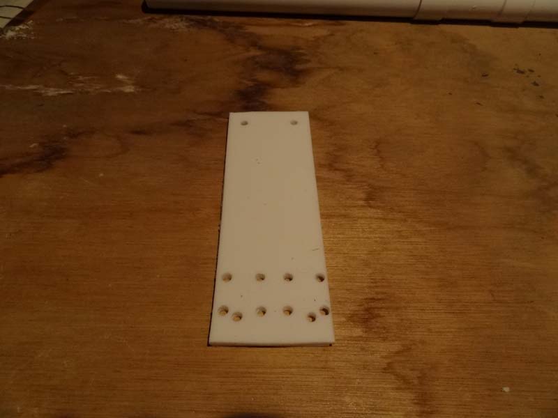
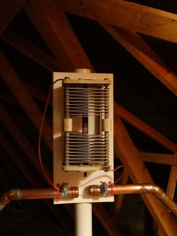
The loop is fastened to the support by using some PTFE sheet and cable ties. Enough room was left on the top sheet at the break in the loop to allow for the tuning capacitor and motor to be mounted.
 |
 |
Upper plate for capacitor and motor. |
Lower plate for Faraday loop. |
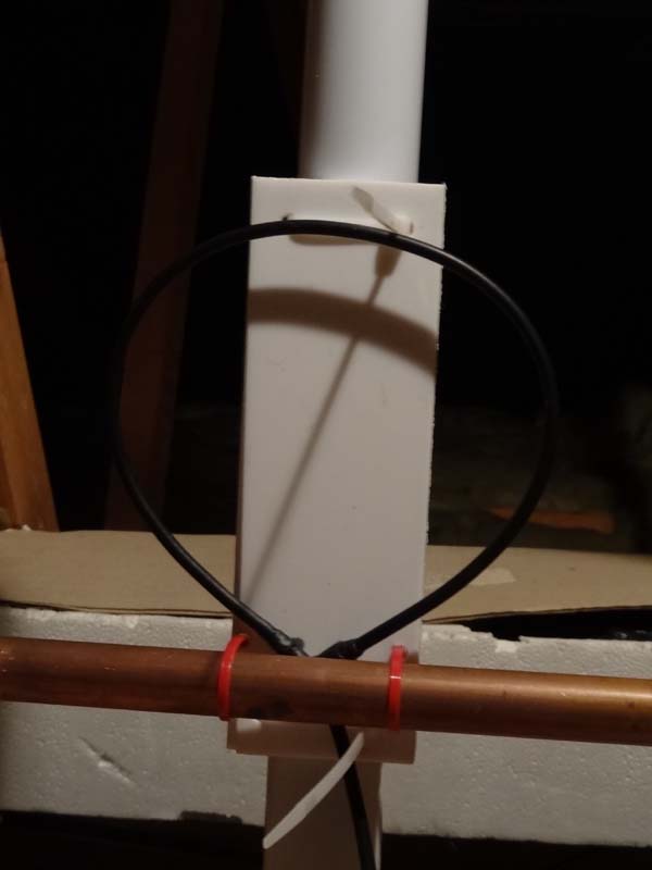 |
I decided to use a Faraday Loop feed again as I had success with this on a previous loop. This was constructed from RG58 coaxial cable. The connection of the inner to the braid has been supported and well insulated using self amalgamating tape. |
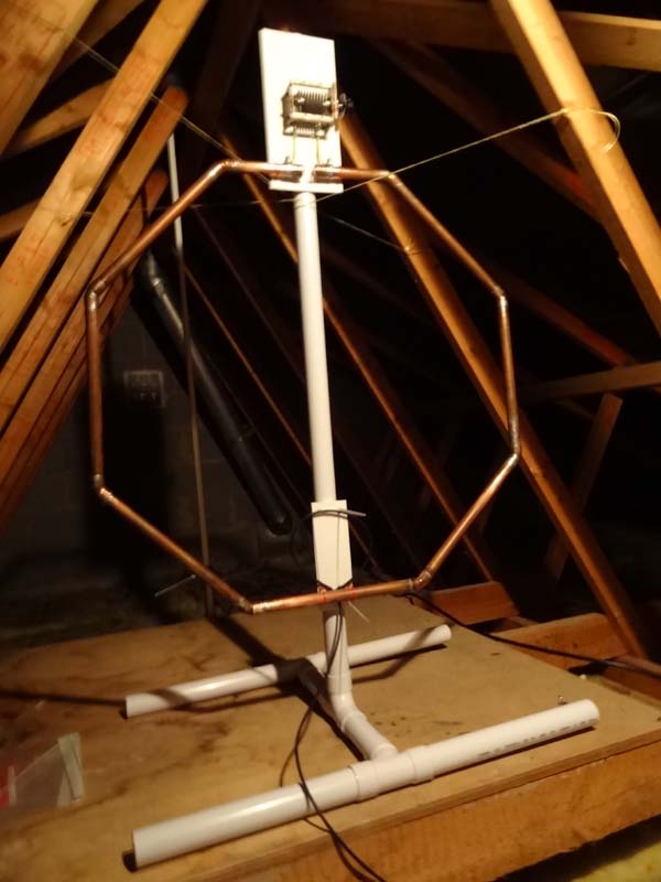 |
I fastened everything together using cable ties to allow parts to be easily moved for tuning purposes. The loop and tuning capacitor are quite heavy and would easily turn the PVC pipe allowing the antenna to fall over. First of all I used building sealant on all unions of the connectors of the PVC support but after allowing these to dry I decided to fix the pipe in to the connectors with some small brass screws to ensure that they did not turn and allow the antenna to fall over. |
 |
Just to try the loop I used a 15pF to 70pF variable capacitor however the next stage of the project will be the construction of a butterfly or split stator capacitor. I first listened on 17m and tuned the capacitor for maximum noise, I used about 5 watts from the FT-817 to tune the antenna and managed a 1.1:1 SWR on 18.130 MHz and then tried 20m with a 1.1:1 SWR on 14.200 MHz. |
Frequency |
S.W.R. |
18.095 |
1.5:1 |
18.100 |
1.4:1 |
18.105 |
1.3:1 |
18.110 |
1.2:1 |
18.115 |
1.1:1 |
18.120 |
1.1:1 |
18.125 |
1.1:1 |
18.130 |
1.1:1 |
18.135 |
1.2:1 |
18.140 |
1.3:1 |
18.145 |
1.4:1 |
18.150 |
1.5:1 |
The antenna has tuned well on 17m and I have used up to 80 watts so far without noticing any flash-over. With the temporary capacitor I have worked the following stations:
|
Date |
Frequency |
Mode |
Pwr |
Callsign |
Sent |
Rcd |
Comments |
Radio |
Distance |
|
27/01/13 |
18.120 |
J3E |
20 |
OE2013O |
59 |
59 |
Josef, Neuhofen | IC-706 MK II | 810 miles |
|
27/01/13 |
18.113 |
J3E |
20 |
OE2013MDI |
59 |
59 |
Max, Hartberg | IC-706 MK II | 810 miles |
|
01/03/13 |
18.133 |
J3E |
10 |
IZ5HPQ |
59 |
57 |
Mark, near Florence | IC-706 MK II | 820 miles |
|
21/03/13 |
18.130 |
J3E |
30 |
LZ135LO |
59 |
59 |
IC-706 MK II | 1370 miles | |
|
13/04/13 |
18.125 |
J3E |
50 |
OH7UE |
57 |
55 |
Manu, Palo, Finland | IC-706 MK II | 1156 miles |
30/04/13 |
18.144 |
J3E |
5 |
HA8JV | 59 |
59 |
Paul, Bekescsaba, Hungary | FT-817ND | 1084 miles |
|
30/04/13 |
18.133 |
J3E |
5 |
LZ833MBB |
59 |
59 |
Bulgarian Club Blagovestnik | IC-706 MK II | 1370 miles |
|
04/05/13 |
18.135 |
J3E |
20 |
IS0FDW |
59 |
58 |
Angelo, Capoterra, Sardinia | IC-706 MK II | 1042 miles |
|
05/05/13 |
18.132 |
J3E |
20 |
Z320T |
59 |
59 |
Al, Macedonia | IC-706 MK II | 1325 miles |
|
25/05/13 |
18.133 |
J3E |
10 |
SV3AQR |
59 |
55 |
John, Patra, Greece | IC-706 MK II | 1483 miles |
|
11/06/13 |
18.139 |
J3E |
20 |
IZ2DPX |
59 |
59 |
George, Como | IC-706 MK II | 644 miles |
|
13/06/13 |
18.132 |
J3E |
20 |
DF8WZ |
58 |
53 |
Stan, Edertal, Bergheim | IC-706 MK II | 463 miles |
22/07/13 |
18.132 |
J3E |
20 |
R3GO | 59 |
55 |
Victor, Lebyazhye | IC-706 MK II | 1632 miles |
July 2013
From the calculations I had made using the various tools available I decided I needed a capacitor of 10pF to 70pF. I found a split stator capacitor for sale on Ebay so took a chance and purchased it with a view to modifying it if necessary. I measured the capacitance at about 12pF to 120pF so it may work if the tools are not that accurate in their calculations.
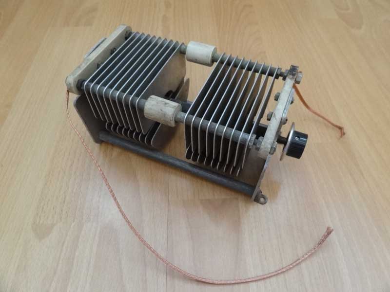
I mounted the capacitor vertically in place of the temporary capacitor and tuned towards it's minimum capacitance. Hearing a strong signal I tuned the antenna a few KHz above then returned to 28.521 MHz and worked Alex, UR9MC, with a report of 55. Not bad for 2.5 watts from the Yaesu FT-817ND! After the contact the highest I could get on 10m was about 28.900 MHz and then I tuned on 12m, 15m, 17m and 20m with a SWR of 1.1:1. To tune all of the 10m band I will need to reduce the capacitance a little bit by removing some plates.
The antenna was used on 17m with the temporary capacitor while I was planning to modify the new one.
February 2014
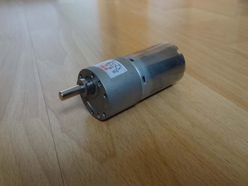
Well six months on and not much done with the antenna other than some use on 17m. I have now purchased a 2 rpm high torque motor and speed controller off Ebay. Ideally I wanted to salvage a stepper motor out of the scrap bin at work and put that to use but did not have the time.
 |
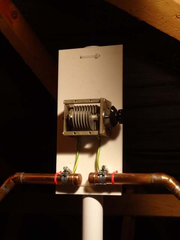
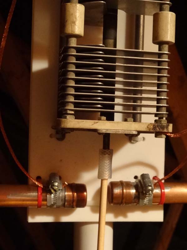
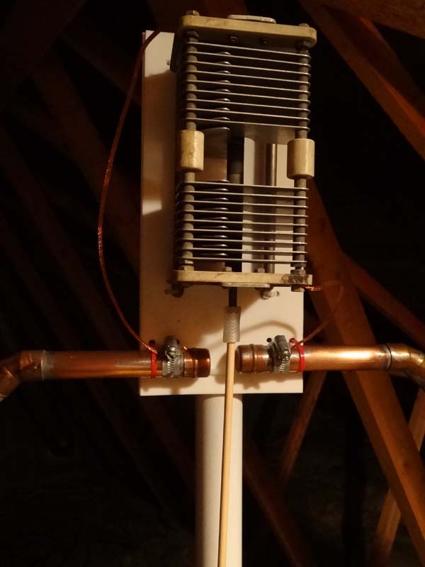
I decided to go ahead and mount the capacitor without modifying it and seeing how low I can tune the loop, I have started using WSPR so thought it would be interesting to see how the antenna performs first. The capacitor was easily mounted, there were some fixing lugs on each corner so two holes per corner were drilled in the PTFE sheet allowing the capacitor to be held in position with cable ties. Connection from the capacitor to the loop was made with shielding from some off-cuts of coaxial cable. |
Due to the weight of the capacitor and the motor I have decided to mount the motor at the base of the antenna and use a long piece of dowl to connect the two. Whilst going through the scrap bin I found some silicone reinforced gas hose that looked the correct diameter so put it to one side for coupling.
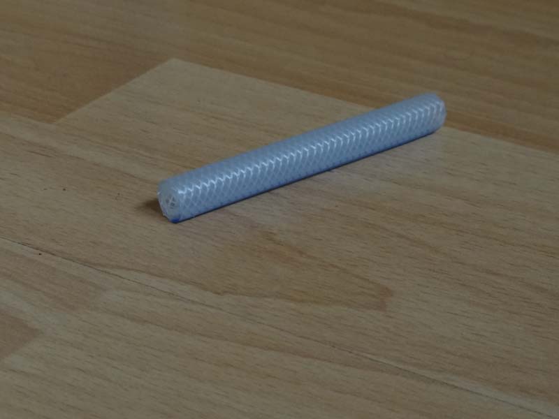 |
I cut the hose down in to some short lengths and it fits snugly over the dowl and capacitor spindle. I backed the tension screw out on the capacitor as much as I can so as to reduce the load on the motor. |
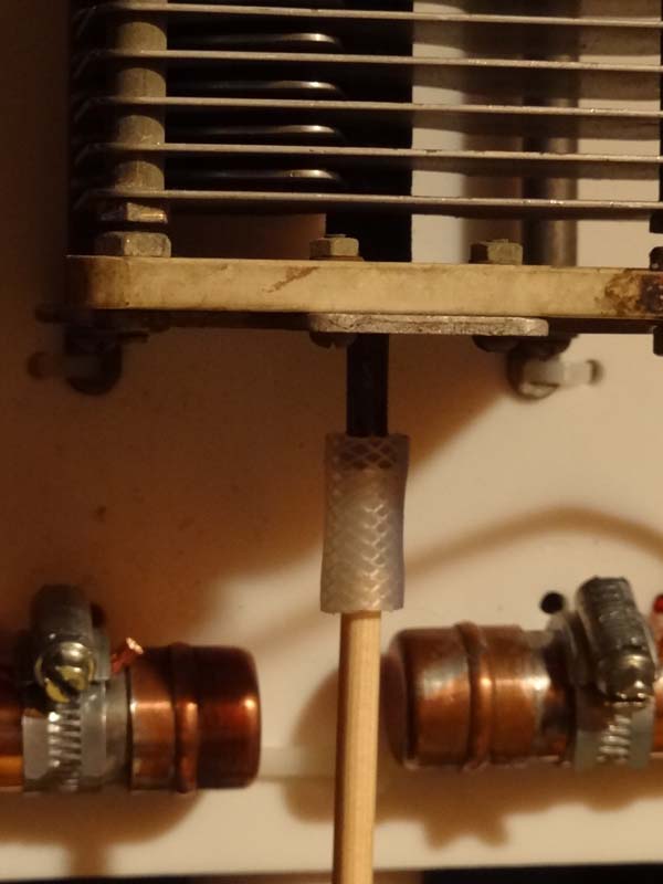 |
The dowling has allowed the loop to be tuned manually without too much effect from myself. It has tuned down on to 30m giving a low SWR so for now I will leave the capacitor alone. I have mounted the motor using some pieces of plastic below the loop and connected it to the dowel using the hose (pictures to follow). I have tried the motor and controller and they work ok but could do with the motor turning a little more slowly and the lowest speed setting, I will get a reduction gear for this. That will be the next stage along with boxing up the controller.
In the meantime the antenna has been used on WSPR on 30m with 1 watt and my signal has been received by N0RW in EL87PR a distance of 4364 miles and best DX on receive was YV4GJN in FK50XF at 7522 Km. Tuning to 20m using 0.5 watt my signal was received by KE7A in EM12KX at a distance of 4670 miles and best DX on receive was ZL3DMH in RE66IM at 18940 Km.