I-LINK BOARD CIRCUIT DIAGRAM

The attached information files should allow anyone to build an I-Link interface
directly onto Veroboard (known as Stripboard in some places).
Component wise its an exact copy of my home made fully working and very stable
I-Link interface that I have here, built on a printed circuit board. The board layout is a combination of the original design from Graeme M0CSH and the board design supplied by Graham G4HFG. It proves to be extremely stable at all times with 100% connection and DTMF functions.
The Vero board design was produced using the Stripboard Magic software
and as far as I can visibly tell should work OK. Although it has to be stated that I have not completed and tried this Vero board design myself as yet.
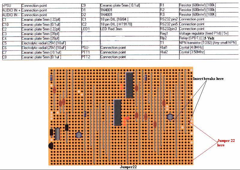
Only a couple of things worth mentioning are observe polarity of polar conscious devices such as Diodes and Electrolytic capacitors. The relay is considered an off board device and should be mounted somewhere and wired into the board at the correct connection points. All other connections i.e. PTT, RS232, Power and audio input are direct board connections too. The VeroInfo.jpg file is as viewed from the component side of the board, please don't forget the track breaks, as it definitely won't work without these HI!!
That's it happy building hope it works OK let me know how you get on.
73's deBill G4VYX Email [email protected]
******************************IMPORTANT***************************
* Due to an error on the enclosed information please carry out the following
modification: -
* Insert track breaks at 19/46 and 18/41.
* Move jumper 22 from 19/26(a) and 32/26(b) to 18/46(a) and 32/46(b).
*********************************************************************