The 5.7 GHz page.....
On this page eventually will be my 6cm transverter and other things. Here's how it's going so far...
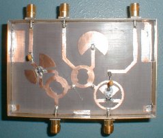
fig.1 The writer's 5.7 GHz dual mixer
This is a 5.7 GHz dual mixer to the W1GHz (N1BWT) design in the ARRL UHF/Microwave projects manual. It's etched on some PTFE laminate. Easily visible in this photo is the receive mixer ( 90 degree hybrid ), transmit mixer ( 180 degree hybrid ) and the LO power splitter ( 90 degree hybrid ). The hp mixer diodes were removed and re-used with care from a pair of old Ku-band TVRO LNB's. The 144 MHz IF ports couple out via 10nF capacitors ( deliberately leaded ). The little V shaped pair of wires on the power splitter are 400 mil long quarterwave chokes to isolate both mixers at the IF.
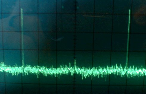
fig.2 transmit mixer as seen on the analyser
I ran a test on the transmit mixer side on the analyser. I used two signal generators to do this. One at 144MHz and another SHF generator running a few milliwatts at 5616 MHz. I booked myself some time on a spectrum analyser to check things over. Shown in the plot is the Lower side mix ( the LO - the IF ) and the High side wanted signal ( 5760MHz ). In the middle is the pip off the LO, around 30dB down on the other two. Both sidebands off the mixer look level and aren't unequal, so this mixer looks pretty good (better than some surplus ones I had tried). Looks like it's time to add the filtering and get this thing on the move ....
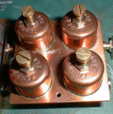
fig.3 The writer's 5.7 GHz pipe cap bandpass filter
This filter's made to the design from W1VT (KH6CP's) design in the ARRL UHF/Microwave projects manual. The pipe caps are British 3/4" (22m stop-ends), two each for transmit and receive. This filter was aligned using a sweep generator and detector, but can also be tuned-up using standard 'go for maximum' techniques.
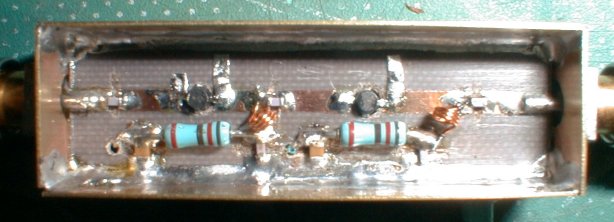
fig.4 The first tx amplifier
This is a two stage MMIC amplifier. I used some ERA-1SM's which still needed a small 'tweak' to get best results. This brings the tx output so far to around 6mW. Notice the small foil tabs around each MMIC to bring up the response to maximum.
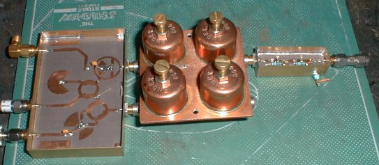
fig. 5 The transverter 'so far'....
back to the microwave radio page