Gardiner MMDS Downconverter LO2398
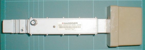
Fig.1 The Gardiner LO2398 Integrated MMDS Downconverter
Click here for the METEOSAT modification page
Summary
Yet another S Band MMDS converter, which is in a very compact package, and contains an integrated antenna feed. This unit has the edge on several alternative types in that it can be run from 12V supplies. The unit is also modular in construction, and lends itself to several interesting modifications.
Introduction
As supplied, the Gardiner LO2398 MMDS converter is a very compact unit, with an integrated dipole-reflector feed. The converter was originally designed to bolt up straight onto a 'BBQ-Grid' type reflector.
There are however a couple of subtle differences when compared to other downconverters. The first being that a microcontroller exists inside the unit with a dedicated VHF receiver, which 'unlocks' the IF and allows signals to pass through, or severely attenuates them depending on whether the command to 'turn on' is received, or not. This is easily countered however as the notes below will reveal. The second is that the local oscillator runs in this unit at 2398MHz, which is of no practical use for satellite reception in the 13cm band, although it is possible to use a 78MHz IF and receive the 13cm SSB allocation. The phase locked loop division ratio is also different, but more about this further on in this document.
The downconverter can me modified for a normal antenna socket (SMA), have a different LO frequency (down to 2000MHz for use with wideband multimode scanners or DC-1GHz spectrum analysers), and be retuned to the 13cm portion of interest. The local oscillator section can be used as-is as a signal source for 2.4GHz downconverter testing (although this is a tremendous waste of a good unit), and also be transformed using the author's modifications into a fully fledged personal beacon with FSK modulation - which whilst still a waste, is a more satisfactory outcome (see further articles).
Circuit description
The RF enters via the integrated antenna (or SMA mount), passing via a first stage GaAsFET amplifier, an NEC NE32684C Then through a stripline filter, much smaller than that seen in the cal-amp 31732. The output from this filter then passes to the other half of the chassis via a feedthrough to the mixer stage which is on a PTFE daughterboard (bolted and soldered to the LO/IF PCB). The local oscillator is generated by a discrete VCO, phase locked to an approximately 11MHz reference crystal, via prescaler and PLL chip as in the cal-amp 31732, but this time the overall division for the PLL is 200, and not 256. A MAR-4 buffers the output of the VCO, and supplies RF at level to the mixer pcb, and a sniff to the prescaler.
The resulting IF is filtered in several stages to prevent 2.3GHz energy travelling down the downlead (the mixer is leaky with regard to the LO at the IF port), before entry into the first of two MAV-11 MMIC stages. The devices have excellent gain and are amply capable of the job, despite being a little current hungry. Further filtration and the signal exits via the F connector. The PSU is a 7808 regulator, and this runs the entire system, allowing easy operation from 13.8V supplies.
Microcontrol of the downconverter is effected by sniffing the IF after the first MAV-11 stage for a VHF carrier in the region of 50MHz. The microcontroller in the absence of this signal chops the IF amplifier on and off at several hertz, and asserts a voltage to an electronic attenuator pair located at the end of the IF amplifier section to effectively shut off the downconverter. Removed and jumpered, this microcontroller is easily defeated.
Opening up the unit
The downconverter is fairly easy to open up. The main problem is the 'external torx' machine screws used to bolt up the lids on both sides of the assembly. A small pair of pliers were used to remove the screws. Some move easily, others eventually comply. It is best not to overdo things and shear the screws however, so be gentle. The screwthreads are 2-56, so replacement screws might be a good idea, unless you own an external torx driver.
The individual plates are held down with silicone sealant. Carefully running a stanley knife along the seam will slowly allow the lids to be parted, revealing the inside. Again be careful.
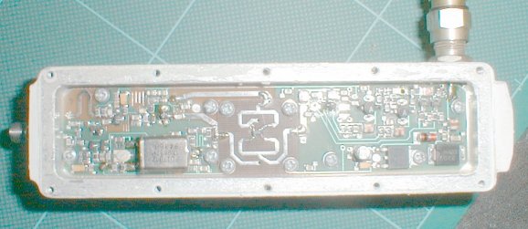
Fig.2 The IF amplifier, RF Mixer and PLL side of the downconverter
Removal of the existing antenna feed
In order to successfully retune the downconverter, it is not possible to retain the original antenna feed. As there are several better alternative feeds available, it was felt that this was no hardship, and therefore the feed could be removed. The approach is to hacksaw gently the outer cover from the feed along the lip of the plastic casting at the point shown. Once the cover has been severed all the way round, the cover and reflector bar (inside) can be removed and put to one side. Inside what remains, there are four screws which are to be undone and removed, putting them to one side.
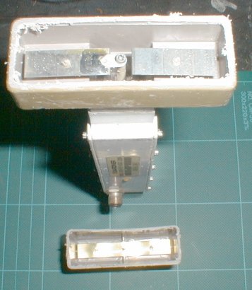
Fig.3 The existing feed cut open for removal
Once this is done, the antenna feed can be removed. The plastic casting is held into the aluminium block of the downconverters case with some silicone rubber sealant. A slight 'worrying' pressure on each of the four faces will help loosen its grip, and then the feed can be pulled straight out of the aluminium casting.
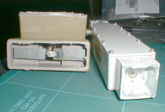
Fig.4 The existing feed removed prior....
You will notice there are four tapped holes, arranged almost in the correct distance for mounting an SMA connector. Indeed two of the holes are in the correct place, but two are just off, and the use of a rat-tail file on an SMA four hole socket is required to just open out the holes enough to allow it to be bolted up. Alternatively open the holes out slightly first with a drill bit, and go from there. Use a very hard and sharp bit as drilling stainless is no fun. Thread is 2-56.
Use an SMA socket that has a solid centre pin, and not the type normally used with a solder bucket centre. Cut the length of the pin to no greater than 3/16" and ensure the end is clean and slightly rounded to allow easy insertion (bull nosed). Use the original screws, and bolt up the SMA socket. That allows now for a coaxial input. Some enamel paint applied judiciously to the exposed aluminium will seal it, and the SMA socket flange from moisture ingress. This painting has worked extremely well on a unit exposed to the rigors of the British weather for the last year.
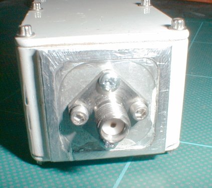
Fig.5 ... to installing an SMA connector.
Defeating the microcontroller (adding operations led)
This is a simple task. The unit was originally designed to work with or without this microcontroller. Just remove the microcontroller board completely, by desoldering the feedthroughs on the IF amplifier side. Undo all the screws on the microcontroller board. Desolder the LED and remove. The microcontroller board should then come straight out.
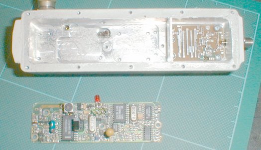
Fig.6 The microcontroller board defeated and removed from the unit.
Jumper the locations shown in the following photograph. This restores constant feed to the MAV-11 MMIC amplifier. You can take power from this juncture to light an LED to indicate power. Use a 390 Ohm resistor in series with the LED. Take the LED to ground on the LED side of the casing by means of an earthing screw from the vacated microcontroller board.
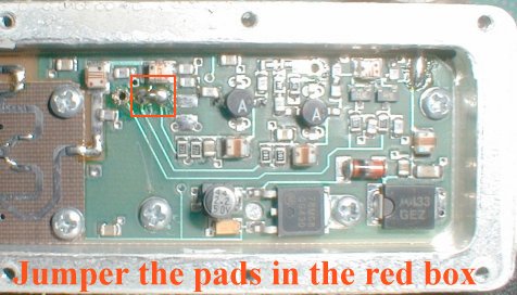
Fig.7 Defeat the microcontroller by jumpering the two pads shown.
Choice of LO frequency
If it is intended to use the downconverter as a receive converter for the 13cm SSB portion, then a crystal change can perhaps be avoided. However with the LO running at 2398MHz, the IF is inverted with respect to SSB signals, USB would be received as LSB due to the high side injection of the LO. Change of crystal can be performed for a 2176MHz or 2256MHz LO. It is believed that there is no need to adjust the VCO for PLL locking (A small extension to the VCO stripline would cover this if it was required).
A 2GHz LO can be obtained with a standard HC-49 crystal at 10MHz, and by extending the VCO stripline as shown in the photograph. Locking is very reliable, but the loading of standard 10MHz crystals is not quite optimum, and the PLL output is around 250KHz or so too high. This cannot be trimmed out. A 2GHz LO does make the use of a scanner quite straightforward however, as one can easily add the '2' in front of the displayed frequency.
Changing the LO to 2000,2176, or 2256 of course restores the low side injection, and allows USB signals to be received at USB as normal. Changing the LO in the case of using the converter at 2400MHz is mandatory.
The author is currently attempting to establish crystal specification, and will add this when it is determined. Although the standard off the shelf type HC-49/u crystal at 10MHz is almost the correct loading, and seems to have a reasonable temperature characteristic - crystals are by AEL. The PLL being the 'next one up' from the one in the Cal Amp 31732 would suggest that crystal characteristics are going to be very similar.
Retuning the front end
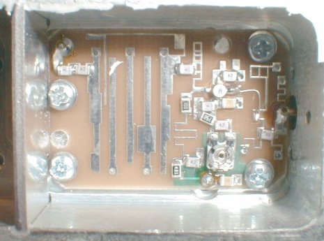
Fig.8 The front end circuit showing the NE32684C GaAsFET
I will presume that you have read the retuning procedure for the stripline filter on the cal-amp 31732 downconverter, and will not duplicate the proceedings here. The striplines are however thinner, and more dexterity is required to work in the confined area. The results however are very good. Attack points are at the extremes of the strip fingers and also on the width of the input and output striplines, and also the large rectangular bulge on the second strip from the right on the photograph.
Improving the IF amplifier response
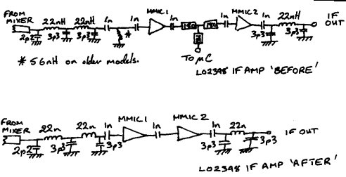
Fig.9 The IF circuit of the LO2398 before and after tidying
Two filter sections and a resistive pad/splitter are present in the IF amplifier. The filter exhibits a low pass characteristic and starts to roll off after 500MHz. The sampler is no longer required, some gain goes down the plug because of this. An inductive trap in the first filtering stage prior to the first MMIC amplifier also provides sharp rolloff from HF to past 144MHz, which is not needed.
To optimise the first section leading from the IF port of the mixer PCB to the first MMIC, we remove the 56nH inductor if present (see later in this section), remove one of the 1nF capacitors which is now suplus, and bridge this with a small piece of wire or tinned foil.
The section between the output of the first and input of the second MMIC can be improved by removing all parts that comprise the sampler and merely coupling the two mmics together with a solitary 1nF SMD cap. Again sections removed can be bridged with tinned foil or wire.
The output section from the output of MMIC 2 needs no further adjustment, except to remove the two electronic attenuators which are no longer needed. Merely desoldering these completes the work.
n.b There are two versions of the IF amplifier that I know of. Early models have a 56nH SMD inductor in the area indicated on the IF amp photo. In later versions this is not present. It is necessary to remove this inductor if present.
The modifications will improve gain, and broaden the response of the IF amplifier.
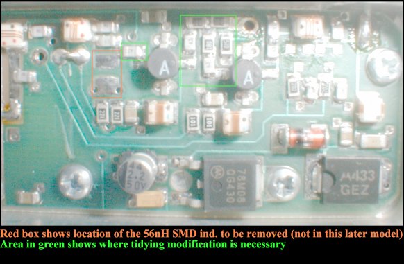
Fig.10 IF amplifier before modification (The attenutors have been removed, top right)
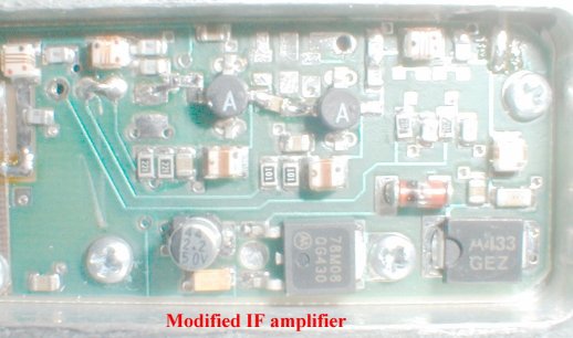
Fig.11 Modified IF amplifier, tided and ready to go
n.b for reliability keep your work clean and neat - deflux afterwards and during desoldering if necessary.
A.M G0ORY First written July 2001, authored HTML August 2002
Back to the 13cm page
any questions please email [email protected]