
California Amplifier 31732
Downconverter
Overview
Originally designed to receive terrestrial television broadcasts
in the Multipoint Microwave Distribution Service (or MMDS) these
downconverters exhibit enough gain and local oscillator stability
to serve as a receive converter in the Amateur allocation at
13cm, once modified. Modification is as basic or complex as
situations allow in the owner's shack. If a wideband multimode
scanner is available (for example, the Yupiteru MVT-7100 and
others) there is no need to perform any modification more complex
than the in-built bandpass filter. Conversely, if only a 144MHz
multimode receiver is available, then a crystal change (more
information in subsequent parts of this document) will be
necessary, in addition to retuning the bandpass filter.
Inside the 31732
What first appears to be an intimidatingly complex piece of
equipment, is in essence the larger portion of a superhetorodyne
receiver in itself. The block diagram is shown in figure 1. In
order to 'block downconvert' the wanted band, the RF signal
'block' is amplified, filtered to remove the unwanted RF spectra,
and then mixed with a local oscillator source to produce a new
'block' at the Intermediate Frequency. Further amplification is
applied at this point to overcome cable losses and to restore the
overall performance.
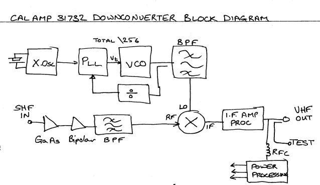
Fig.1 Cal Amp 31732
Block Diagram
A phase locked loop Local Oscillator is used to mix down the
signals to the IF. The PLL consists of four components. A crystal
oscillator reference, a PLL chip, a VCO operating over the
appropriate range, and a prescaler to divide down the VCO output
for comparison in the PLL IC with the reference frequency. The
phase locked output of the VCO in the converter is normally
2278MHz. The whole PLL system divides this by a total of 256 to
compare with the reference crystal. Therefore, To change the PLL
frequency, we change the reference crystal.
Modification
Unconverted the units do not have sufficient sensitivity to
receive signals, except the strongest, gain being many dB's lower
at 2320 and 2400MHz than the MMDS portion. Retuning the filter,
in the case of the satellite allocation at 2400MHz is not
unnecessarily complex, and the entire filter can be slabbed with
a sheet of teflon shim to bring the filter resonance back to
2400MHz. A piece of 0.015" teflon sheet or tape is stuck
directly over all the filter resonators. This is the simplest
modification possible, and is a compromise.
In the case of retuning the filter to work at 2320MHz (the 13cm
SSB section of the band), further work is required, and in fact
the technique is equally applicable at 2400MHz, and provides
superior results to that obtained by the use of teflon shim/tape
alone. With this modification further test equipment is
desireable, as it is necessary then to provide a variable signal
at the signal frequency, and a means to monitor that signal and
peak up the filter for best response.
Using small pieces of copper or brass shim 0.001 or similar, it
is possible to move the filter right onto any frequency in the
13cm allocation, and obtain best performance. These are
individually tinned, and brought over the existing stripline
until an improvement can be obtained, whereupon they are soldered
in place, repeating the whole excercise until no further
improvement can be obtained. Many tabs and a fair amount of time
and skill is required to obtain the best results. Reference to
the appendix included with this document is advised for this
procedure - it is the author's preferred method. Working ones way
from the output side of the filter to that of the input is the
method to adopt when retuning this filter.
One usable scenario for retuning is illustrated in figure two
below. More sophisticated test equipment can of course be used
instead. The basic idea is merely represented here, but the
system outlined does produce good results.
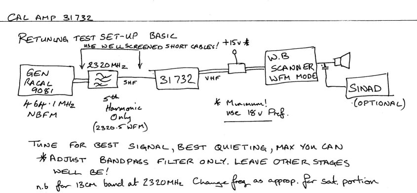
Fig.2 Retuning setup
with basic equipment
Note that more exotic equipment could be used (and the author posesses this), however the equipment above gives good results, and is in the author's estimation, typical of the intermediate UHF experimenters equipment inventory.
Note that it is very important to not manually tune this filter
for the highest S meter reading, the mixing process produces not
only the wanted signal, but an image signal (which will be
noise). Tuning for best S meter reading will allow more of the
unwanted 'noise' to interfere with the wanted signal, the result
being a large reading on the signal meter, but potentially poor
performance with weak signals. Tuning the downconverter for best
quieting and signal/noise (or SINAD) will improve matters
considerably. Access to a SINAD meter is not so important if you
have good ears, and can tell the difference in quieting. It is
not necessary to adhere to this when 'cladding' the filter with
PTFE, as you will have to accept the results obtained by this
method. The author is very lucky to have good hearing, and can
equal the results obtained with a SINAD meter. An oscilloscope
connected to the receiver's output will aid manual retuning to
some extent by examining the roughness of the modulation. Results
of retuning by hand with the author's preferred method exceed
46dB of image rejection at 2401MHz with a 145MHz IF. This is
quite adequate.
As was said earlier, if a multimode wideband scanner is
available, or a receiver capable of receiving all-mode at 42MHz
or 122MHz is available, then the local oscillator reference
crystal will not need to be changed. Once the filter is tuned,
the signals from either the 13cm SSB or satellite portions will
be easily received.
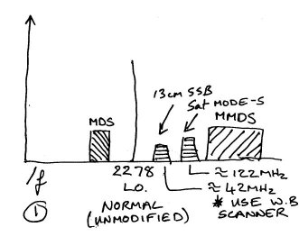
Fig.3 The local
oscillator at 2278MHz can be used without modification to receive
13cm signals
However if only a 144MHz SSB receiver is available then the local
oscillator will need changing to either 2176MHz (for 13cm SSB) or
2256MHz (for the satellite portion). A crystal is easily
obtainable from Hy-Q (now Precision Devices International) and
the frequency calculated from the function below...
Crystal Frequency = Local Oscillator
Frequency / 256 ( all freqencies in MHz)
Crystal is in an HC49/u holder, 33pF load capacity fundamental,
accuracy is 10ppm over -30 to +60 Celsius.
The crystal can be ordered from Hy-Q with the following ordering
code:
QC49 FUNDAMENTAL [xtal frequency in MHz] FG05F
And is of identical performance to the original quartz crystal
used in the unit.
A more economical alternative is from Quartslab Marketing in the UK, a set of test crystals were ordered, and found to be of identical performance to the Hy-Q units. Details from the author on request.
For a local oscillator of 2256MHz and 2176MHz no further
adjustment to the LO circuitry is needed., other than the crystal
change. The photographs show the authors unit, tuned at 2320MHz
with a 2176MHz local oscillator, with the transveter LO tap (see
end of this article).
The received IF will then be available at 144MHz. Once the
crystal is changed, the operating frequency can be easily
adjusted with a frequency counter by means of the trimmer
adjacent to the crystal. Remembering that if measuring the
frequency of the crystal oscillator, any error in trimming will
be multiplied by 256 at the Local Oscillator frequency.
A 1Hz resolution at 8-10MHz is desirable if measuring crystal
frequency. 10Hz at signal frequency. Several alternatives for
measuring the Local Oscillator frequency are available, and the
author posesses a Watson 3GHz counter which with a 30MM insulated
probe works most satisfactory. An EIP Microwave counter was also
used with higher precision still. Wavemeters will not be accurate
enough at the LO frequency for any more than an indication of
operation. Of course if your alignment signal is calibrated then
the signal can be netted by zero beating, or even an HF receiver
could be used to get the crystal frequency close.
When calibrating the crystal oscillator, bear in mind that there is always a little uncertainty, and that there is some 'backlash' in the adjustment due to the loop on the PLL. Shoot for 250Hz accuracy on setting as the trimmer is 'all or nothing' - I can get 70Hz, but only after compensating adjustments, and around 10 minutes work; be prepared to put in some time on these, and allow at least an hour to let things stabilise before any adjustment. That goes for your frequency counter too - they aren't 'WWV on demand' to coin a phrase. The room or workshop in which you perform the adjustments should be stable in temperature too, matching to your normal average ambient temperature is ideal.
DC Injection
In the event that your receiver is incapable of supplying the
16-25V required at 1/4 A (and it is suggested that the
downconverter be run at no less than 18V) then a power inserter
will be required. Desireable characteristics are a sealed unit
that prevents leak-in of strong signals on the IF frequency from
local sources, sufficient bypassing at RF of the DC supply, and
low insertion loss. A suitable unit can be home made with nothing
more than a scrap of PCB, a sharp knife, some 1nF capacitors, and
a VHF RF Choke. Accompanying figures show a suggested layout.
There is some leeway in component values and tolerances are not
critical. A PCB will be made available if desired. It is
recommended to use SMD capacitors and good feedthroughs for best
results, however the experimenter can work with whatever
materials are closest to hand. Keep all lead and line lengths
short.
Since this document was prepared, as an
excercise, a DC inserter was fabricated from a small diecast box,
with an F type socket on one side, and a BNC flange mounted
socket on the other. Power was brought in via a panel mount DC
jack. A 1nF AVX radial multilayer ceramic capacitor (chip cap
with leads in an epoxy blob) was used to span the two RF
connectors, and a VHF RFC was taken to the DC jack. This
arrangement works extremely well. The SMD alternative is still
favoured, but for robustness the diecast box definitely has the
edge
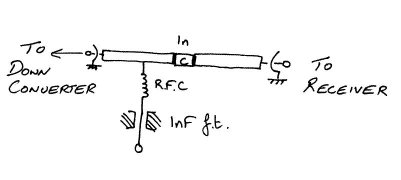
Fig.4 DC Injection to supply the
downconverter, striplines are approx 0.1" wide on a small
piece of D/S PCB material
Transverter
It is indeed possible to use this downconverter as a basis for a
13cm transverter, and as such offers good performance at an
advantageous price. A tap from the local oscillator can be
obtained by insertion of a 30mm probe situated above the first
local oscillator bandpass filter's stripline, and spaced
equidistant from the top surface of the pcb and the top of the
lower casing. It is awkward to mount a suitable connector in such
a confined space, however an SMC connector will fit into the
available space easily. Some removal of the diecast casting on
the exterior is required, caution being required not to overdo
the 'milling' or getting metallic dust inside on the surface of
the printed circuit board.
Positioning of this probe tap yielded some +4.5dBm of LO power as
measured on the author's HP432A power meter. This was ample to
drive a balanced mixer to produce 2320MHz with milliwatts of
144MHz drive. There are several designs for 13cm transmit mixers,
however the author has developed a suitable transmit mixer with
parts salvaged from an Ionica subscriber unit, with a low level
amplifier capable of driving a PA to whichever power level as
necessary. A PCB layout (G0ORY-005) is also available, and can be
fabricated with 'press'n'peel'. however the design is still in
the beta stage at present, but the design is available on
request.
The transmit mixer is online here - http://www.qsl.net/g0ory/2.3g/005/005.html
Portable operation
A suitable design by Peter G3PHO is included with these papers
and represents a useful portable DC source for the voltages
required by the downconverter. Acknowledgement to Peter and his
excellent Microwave Newsletter are given herein. Peter has much
information available at his website - The world above 1000MHz - http://www.qsl.net/g3pho.
A.M G0ORY QTHR 07.2002 [email protected]
Appendix - retuning the stripline filter
on the 31732 downconverter
Using strips of thin copper (.001" brass should work too
K&S metals shim kit from hobby stores) I first cut the foil
into strips more or less the same width as the filter lines. Then
clean both sides thoroughly with a fibreglass pencil until it's
really really clean, and tin with the least amount of solder
possible. Run the iron up and down the length of the stip whilst
holding it by the end in a pair of tweezers, and first let
gravity do the work and let excess solder run to the bottom. A
sharp flick of the tweezers whilst the tin is molten shakes off
the bulk of the excess. Second, run the iron up and down the
strip once again, and flick the excess off, so there is as little
solder as possible on the strip. get some cotton buds, and some
nail varnish remover - cheaper stuff is better as it contains
less oils, a large bottle costs just over £1 and lasts years (or
pure acetone, ethanone flux off, isopropanol - sold as 'head
cleaner' 1.1.1.Trichloroethane - sold as 'tipp-ex thinners' ),
soaking a bud in the mixture and then cleaning thoroughly all
traces of flux and residue from the strip - you'll be surprised
just how much comes off! Whilst at the chemists with this little
shopping spree, get some wooden toothpicks too, a small box will
last years.
Open up the unit, making note of the general layout of the
filter. The filter consists of alternate 'u' and 'n' elements -
referred collectively as a 'hairpin filter' No board traces need
to be cut, which is a godsend because the modification is at
least reversible. If you make a mistake, remove the wrong piece
and start again.
Remember, use a good earthed soldering iron, and earth the work,
preferably by strapping the negative of the power supply to
earth. A good earth arrangement is essential to save any damage
caused by static. It's just plain good sense too. Remember also
that you should power up the converter only when checking the
results of your efforts. Always power down when you're soldering
- it's easy to harm it if you don't! A rigid discipline and a
systematic approach is a must. Also only work on the equipment
when you are well and able to do so, and not when tired, under
the influence, or agitated. A clean soldering technique is
advisable. Regularly clean the iron before each soldering
operation, and use a minimum of solder. Dross, contaminated flux
residues and bad tinning will cost you dearly in the long term,
with intermittent losses of sensitivity, thermal intermittents,
and other nasties.
Note that on some units there are dabs of solder left at the
extremes of the hairpin elements to effect tuning. These can be
removed with desolder braid (Chemtronics Chem-Wik Like is
recommended, ordinary desolder braid doesn't mop as well). Then
clean the board with a cotton bud again to remove flux, then use
the dry end (the one you didn't dip in the stuff) to dry off the
board. Desolder braid is a handy thing to have. Don't even
contemplace using a solder sucker - the percussive blows from
these do more harm than good, and in any case it's ineffective.
Also, when the techs at cal-amp tuned the board up for MDS/MMDS
use, they used sharp knives to cut traces on the board. They were
a bit heavy handed, and sometimes gouged lumps of dielectric out
of the board, leaving a mixture of dead trace and fibreglass
sticking up on the board. Using a small sharp scalpel or fine
knife gently lever and scrape away this mess, and try not to make
any more damage than is already there. This helps makes a cleaner
job. If you get dust or bits inside the unit that just plain
won't come out, use a photo puffer brush, clean blusher brush
bought purely for this job (not one smothered in makeup!), or
canned air to shift it.
Get both of my photographs of a modified unit to hand and study
them well. This gives you the insight into the attack points for
retuning.
Right, you're connected up, with your receiver monitoring for the
correct conversion, the signal generator switched right down to a
safe level (lowest possible to start), and the unit powered up
without its lid in front of you. Let's begin.
Advance the signal generator, until noise is detected on the
receiver. Use only as much signal as is necessary to get a
noisy-ish signal out of the unit. I'm going to refer to using the
noise and level on a wideband FM signal (50KHz) here to do my
alignment, but if you have a clean enough generator, you can go
SSB straight away, and listen to the loudness and signal reading.
You can tune the filter now, try the unit out, and see if you
need to change the local oscillator crystal. The IF amplifier is
broad enough to work okay at 42MHz for 13cm SSB, and at 122MHz
for 2.4GHz. At 144MHz IF's for 13cms it's still very good.
Looking at the first resonator, where the stripline couples into
it, you'll notice some small traces arranged in a square. Moisten
the sharp end of the toothpick, and pick up a piece of that
tinned strip around 3/16" long. Put the strip in the area
indicated and move it around, watching for an increase in signal
coming out. You'll notice a useful increase. When you get the
largest increase you can. Remove power to the downconverter, hold
the toothpick fast, anchoring the tab, and just touch the
soldering iron to the strip end. Solder will flow easily because
everything is clean. It's soon soldered, so don't spend all day
with the iron on the strip! Wait for it to cool and remove the
toothpick. Turn the power back on, and check that the increase is
about or better than the increase you had.
Take another piece, same length (cut several and have them laid
out ready), and waft in direct contact over the first piece you
applied. If you get more signal, do the same as before and solder
the new piece in. If not, move onto the next stage.
On the resonators, it's best to lengthen only one side of the
resonator hairpins at once. Find with the toothpick arrangement,
which I'm sure you're familiar with by now which side gives most
signal and stick with it. Sometimes the length of strip will be
at an extreme, others will hardly extend the original trace at
all. This doesn't matter. Each time remove power, solder in, and
power up again to check. You should now be reducing the signal
generator after each piece is soldered in to a noisy or weak
signal to ensure that you find the sweet spot that gives most
increase.
When one extreme is done on these hairpins, it's always the
opposite extreme on the next hairpin which provide the best
increases. The pattern snakes across the entire filter in this
way. After you've worked on the filter all the way from the input
side to the mixer you're about done. Note the decrease in the
level of signal generator input required now from what you
started with. This corresponds to all that lost gain!
Wafting these little tuning strips around the second stage tuning
after the first GaAsFET amplifier didn't give any improvement in
signal, leave well alone here - in particular don't adjust the
wire loop on the input to the GaAsFET in any way, leave well be!
This decides the noise figure which is already good in this case.
Only re-adjust with a noise figure meter, if you are fortunate
enough to have access to one.
To get the best out of the filter at 2.4GHz is easy. When you're
done, you can try wafting the tuning pieces over the other traces
around the filter, like the notch elements to see if you can get
any more improvements, or over the entire filter hairpins again
to see if there's anywhere you've missed. Stop when you can't
find anywhere to improve. It gets silly and too time consuming
after this.
I went for absolute max on mine, and started looking at the
coupling between resonators and the width of tracks. I managed to
claw back an extra 10dB+ of sensitivity compared to what it would
normally be at 2.3GHz with the filter mod I've described above.
If you're sure of yourself and patient, you can follow my work
and get the maximum out of the filter. With the normal mods, I
was able to receive my local 2.3GHz beacon (only running a few
watts erp out of its zero gain antenna at over 10 miles away) at
my shielded QTH in the workshop at around S5 on a 'tin can
(circular WG) antenna - many reflections could be received. After
further work, it was much stronger still, and easily received
with 30mm of bare wire inserted into the N socket alone, down in
my workshop in an extremely unfavourable location for reception,
QED.
Image rejection (FLO-FIF) >=46dB with this method, more than
adequate.
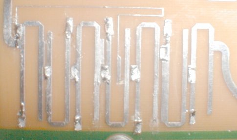
Fig.1a A retuned
downconverter hairpin filter using the author's method, for
2320MHz
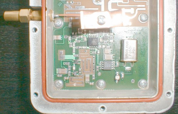
Fig.2a The 'transverter tap', showing
the LO crystal for 2176MHz and the tap probe (terminator
attached)
Further massaging of the noise figure on the first stage could be performed with the aid of a PANFI, or G4COM alignment aid. In the author's and several other's experience however, the overall performance is more than adequate. If you have the test gear, it is a worthwhile persuit. The author finds now that once retuned, CW performance at 2401MHz is almost 6dB improved on the original CW performance at 2500MHz, which is very encouraging, and units exhibit >=46dB image rejection at 2401MHz with a 145MHz IF. This was after a recent test with both a levelled CW source and spectrum analyser.
A.M G0ORY. First written July 2001, Authored HTML August 2002
For enquiries or clarifiication please email me
at [email protected]
Back to the microwave
radio page
You are visitor number since
07/15/02