The Magnetic Microphone
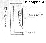 This microphone is very like a loudspeaker. It consists of a very light
diaphram which is connected to a coil. This coil is suspended in a magnetic
field from a permanent magnet. The sound waves are converted to an electrical
signal by the movement of the coil in the magnetic field.
This microphone is very like a loudspeaker. It consists of a very light
diaphram which is connected to a coil. This coil is suspended in a magnetic
field from a permanent magnet. The sound waves are converted to an electrical
signal by the movement of the coil in the magnetic field.
This works in a similar way to a dynamo or generator, but instead of generating
a constant stable sine-wave output it generates an output in sympathy with the
audio signal vibrating the diaphram.
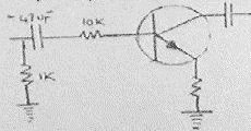 Typical Microphone Input Circuit.
Input is typically via a 47uF capacitor - this is the DC blocking capacitor and
the value is chosen to allow AC at audio frequencies (AF). The output will
also have a DC blocking capacitor. This is effectively a pre-amplifier and the
output is further fed to an amplifier.
Loudspeaker
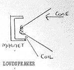 The loudspeaker is driven by an amplifier. The output from the amplifier is
changed to a magnetic signal by the coil. The interaction of this magnetic
force with that of the permanent magnet causes the coil to vibrate in and out
and this is what drives the cone.
The loudspeaker is driven by an amplifier. The output from the amplifier is
changed to a magnetic signal by the coil. The interaction of this magnetic
force with that of the permanent magnet causes the coil to vibrate in and out
and this is what drives the cone.
This is the reverse action to the microphone and works in a similar fashion to
an electric motor. The signal, which represents the audio alternating in the
coil causes movement with the magnet and vibrates the diaphram in sympathy with
the input signal.
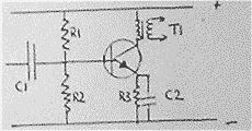 The amplifier (left) operating in class A is typical of an amplifier used to
drive a loudspeaker in many small applications. A more efficient configuration
of audio amplifier is the push-pull circuit. This configuration is used for
class B amplification as only half the waveform is amplified in class B, each
half of the push-pull circuit amplifies a half cycle of the wave.
One transistor deals with the positive half-cycle while the other deals with
the negative half-cycle.
The amplifier (left) operating in class A is typical of an amplifier used to
drive a loudspeaker in many small applications. A more efficient configuration
of audio amplifier is the push-pull circuit. This configuration is used for
class B amplification as only half the waveform is amplified in class B, each
half of the push-pull circuit amplifies a half cycle of the wave.
One transistor deals with the positive half-cycle while the other deals with
the negative half-cycle.
The Class B audio output stage
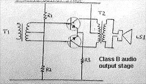 The audio input enters via T1. Each transistor amplifies one half of the
cycle. T2 is used to match the impedance of the output transistors to that of
the loudspeaker.
The audio input enters via T1. Each transistor amplifies one half of the
cycle. T2 is used to match the impedance of the output transistors to that of
the loudspeaker.
|