.jpg)
Build the "EI2IV HAMMOCK".
This antenna is not a new antenna and was in use long before I was even born. This is just my way of constructing one "at little or no cost" that looks a little different to the usual designs I have come across. I hope you like it and that it is of some help to you and may-be saves you some money also :-) I have mine up now for almost 4 years and it has survived several storms and it works well.
This is the 5 band dipole antenna, I call it my "HAMMOCK" as it resembles one sideways, the VSWR is flat across all of the bands. The 1/2 wave dipoles are cut for 40/20/17 & 12 meters the 40 meter dipole also works on its 3rd harmonic of 15 meters the VSWR rises a little on 15 meters to abt 1.6 : 1 but if I tune this I will upset 40 meters which is flat so I will live with it. Use the usual formula to find the dipole lenghts ( 468/frequencey) and leave about 6 inches over for tuning.
The 40 meter element has to support the entire weight of the antenna and feeder so use heavier gauge wire on the longest element. I used 1.5mm square pvc coated multi strand copper for the lower 3 dipoles & 6mm square similar copper for the top dipole simply because I had a roll of both sizes 4mm should be plenty for the top dipole.

The centre plate is also a bit heavy 1/4 inch Perspex from the junk box, the feeder is RG58 coax, and an old commercial dipole centre again from the junk box, Unfortunately any heavier coaxial cable will cause it to sag (unless a centre support is used). You may also want to add a Balun I don't have one and mine works well or better still feed it with a balanced line.
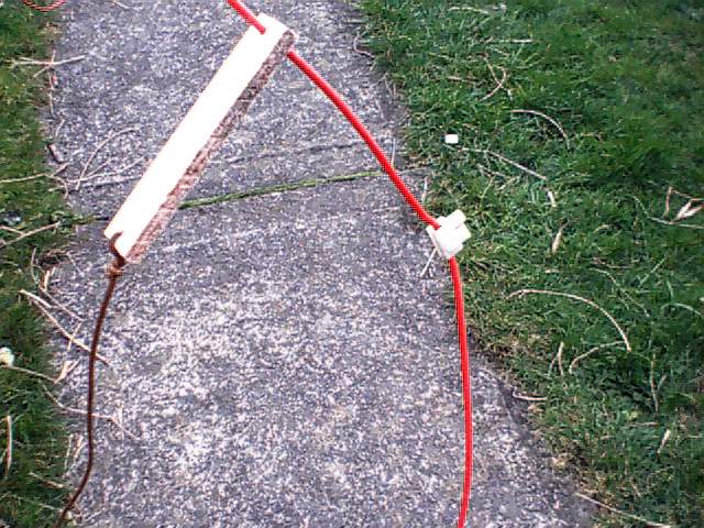
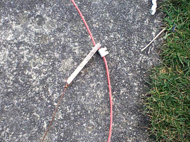
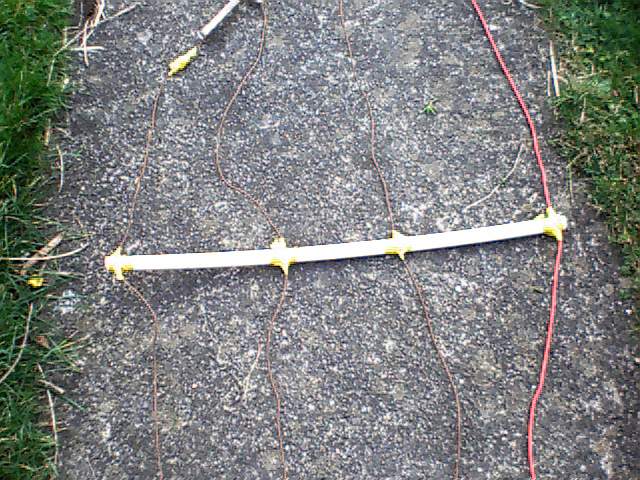
Dipole spacing is not too critical mine is about 2 inches on the centre plate up to about 6 inches on the 20mm light pvc pipe spreaders (commonly used here for an overflow outlet from attic water tanks) the end insulators are about 5 inches long bits of scrap flat fibreglass just drill 2 holes for wire to pass through, tie a loop on the lower dipole on each insulator a temporary job until you have it all tuned, on the upper dipole on each insulator slip on (before the insulator) a single "block connecter" I call them, (you may call them electrical connector, choc block not sure if they have a name really) string up the longest dipole between 2 points about 5 feet above ground so you can assemble it, slip another connecter & insulator on to the second dipole (same for the 3rd dipole etc) tie the end of each dipole to the end of the insulator hanging from the dipole above (temporary as you may need to undo it a few times to prune an inch or 2 to tune) stretch the top of each insulator out along the dipole it just hangs from when it is tight tighten the connector against it to hold it in place don't over tighten or you will cut the wire just take a little bite in the pvc wire coating . On the pvc pipe spreader drill 4 holes about 6 inches apart n run the wires through drill the holes so the wire is not loose, position the spreader to shape, I just tape up the wire on both sides or each hole with pvc tape.
Tune for the best VSWR starting with the shortest dipole first, I used my MFJ 259B antenna analyser for ease . I have a pulley on both supports so I can drop it in seconds prune it rise it and drop it again etc.
You can have as many bands (dipoles) as you like on this design. The transmitter sees reactance on all dipoles apart from the band which you are tuned to and so ignores them. Remember this is not the case at the 3rd harmonic hence no 15 meter dipole is required. Let me know if you or your friends build one or have any ideas on improvements to my design of it. How about building one from top band up to say 40 meters for Field day? Have fun!
Back to my Home page.