- Luxman System Bus I Interface
- After years of best-buy searching, I ended up with the following Hi-Fi components:
- KENWOOD GE930 Stereo Graphic Equalizer
- LUXMAN A-383 Stereo Integrated Amplifier
- LUXMAN D-355 Compact Disc Player
- LUXMAN T-235 AM/FM/LW Stereo Tuner
- PIONEER CT-S630S Stereo Cassette Deck
- SONY MDS-JE510 Minidisc Deck
- This set, connected to a pair of JBL's Control 1 and Control SB1 subwoofer,
finally looked a complete nice system to me. The only problem I found was
that, although the A-383 remote controller could control CD,TUNER,TAPE1 and
TAPE2, I could only send commands to the CD, which actually was the only
known 'family' for the amplifier. Even the Tuner, which also was Luxman, was
System Bus II compatible, so it wouldn't communicate with the amplifier either.
I took a look at a pair of cool universal remote controllers from SONY and ROTEL,
but the price was far out of common sense's range.
- So I decided to study the System Bus I protocol and interface each Hi-Fi component
by means of a PIC microcontroller. Each module would have a pair of input jacks for
daisy-chaining all of them to the System bus coming from the amplifier, which is
the one that receives the IR codes and transmits commands through the bus. The
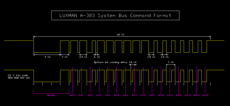
commands had the following format:

- The bus is a simple 5v/0v TTL signal. The modules have the input and output connected
internally, with high impedance imputs and open colector outputs. As you can see on the
picture, the easiest way to receive a command is just skip the header, look for a
falling edge of the signal
and when found, wait 1.2ms. Those 1.2ms are the optimum delay for getting the status
of the bit, since we get the widest safety space at both sides. The voltage on the
bus line after the delay is the binary status of that particular bit. If you look
at the PIC16F84 code I wrote, you can see how easily the receiving routine is
implemented. After receiving the command, the PIC in each module has to decide if
it has to respond to that command or it was sent to someone else.
- Here is the list of the available commands:
Luxman A383 System Bus Codes
- In order to take advantage of the timer and sleep function of the T-235 tuner,
this particular unit should also be capable of sending signals via the bus,
not only to 'listen' to it. This resulted in a more complex programming in
the PIC for the tuner, because it should listen to the commands and also be
capable of sending a shutdown, or power-on, command to the system when the sleep,
timer, or it's ON/OFF button was pressed. At any given time, the program running
on the tuner should know if the system was on or off, and 'press' it's own power
button when a shutdown command from the amp was received. This way, the system
could be turned on/off via the power button on the amplifier, the power button,
on the tuner, power button on the remote controller, or via the timer/sleep
function from the tuner. That was the kind of flexibility I was looking for.
- I decided to plug the AC cords from the EQ, MD and MC to the relay-controlled
AC output of the tuner so I could free one pin of the pic for 'pressing' other
buttons and also use the TIMER switch on the MD and MC. This way, they would not
respond to the SYSTEM-POWER-ON or SYSTEM-POWER-OFF commands, but they would
start playing/recording whenever the system was switched on.
- The other interfaces would have a 1Mohm resistor at the line bus input, so they
would not degradate the signals on the bus. The 'pressing' of each button in the
module is done with the aid of one 4N35 optocoupler included in the interface.
This way, we don't have to worry about the particular design of the button-matrix
built on the modules, and the PIC is protected from the signals that could be there.
It also allows the buttons to work as usual although connected at the same time to
the inteface. It took me some time to come up with that solution...
- This is the commented code for the PIC 16F84 placed inside the tuner:
t-235.asm
- I've only included the file for that particular module here because is the one that
performs all the functions I've implemented. You will only need to study it a bit
(that's what I commented it for !!) to understand how it works and make the changes
you need. I've included an additional signal (and LED) that flashes when the interface
is powered and after a valid command is received. It is too fast to be seen, but if
you capture the signal with a DSS or logic analyzer, you can see the code extracted
from the signal on the bus, assuming it was valid according to the expected scheme.
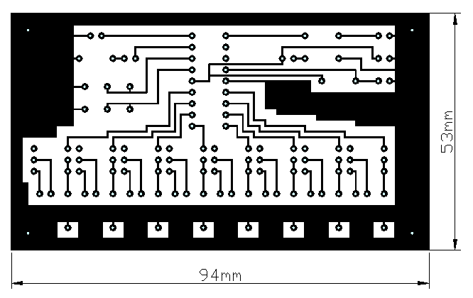
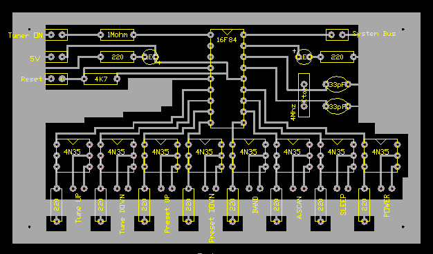
- Here are the PCB and silk view of the board for the interface that goes into the
tuner. The PCB picture shows what you should see if you look to the tracks side
of the PCB directly. Be careful because depending on the method you use, you could
have to mirror it prior to printing. The silk view represents how the components are
placed on the board, as viewed from the top.


- I've built one of the interfaces for each one of the modules. The only thing that needs
to be modified to suit your personal needs is the code running inside the 16F84. If there
are components on the PCB that you don't need, just don't install them. My system has been
working for two years by now without a single problem.
EB4EQA's Projects Home


