![]()
(Miscelánea)
Note: The following projects were gathered from the internet, therefore the author does not endorse any of the projects, they are on your own risk.
(Nota: Los proyectos siguientes se recogieron de internet, por consiguiente el autor no garantiza ninguno de los proyectos, ellos son bajo su propio riesgo.)
Direct Digital
Synthesizer Kit
N3ZI DDS 2


1) 1Hz step size. This was the most requested improvement, and this chip has it. Furthermore the LCD will display the frequency with 1 Hz resolution. I'm going to set the step size to something higher than that, but those of you who demand precision will be able to change the default step size. The LCD display will show 9 digits of frequency (a sign, 2 megahertz digits, 3 kilohertz digits, and 3 Hz digits.
2) No (or very little) overclocking. All these kits will be shipped with 80MHz clock modules. This along with an improved output filter will allow operation up to 34MHz.
3) Fast RIT and FSK. This chip has two frequency registers, and there is a direct connection to select between the two. Switching is instantaneous and phase continuous, you can use it with CW QSK and even FSK (RTTY) is you want. The push switch on the rotary encoder allows you to set the RIT offset, tuning speed, and calibration.
4) Vastly improved Encoder tuning. The dial now operates much like an analog VFO dial. I have an acceleration algorithm that works very nicely, so the push switch for speedup is no longer required. New debounce and other changes make the action smooth like an optical encoder using an inexpensive mechanical encoder. There is no lag for the LCD, and no queuing, no glitches, and catch-up.
5) Phase continuos frequency changes. The old chip had to be turned off then back on for a frequency change. So there was a brief but noticeable glitch. The new chip has phase continuous frequency changes meaning than the instant a new frequency is selected, the output waveform continues smoothly by sloping and the proper rate for the new frequency
Features and Specifications:
1Hz user tuning steps
User settable rate via tuning knob
0.3Hz internal step size.
Glitch free, phase continuous tuning.
Virtually indistinguishable from an analog VFO
Very fast tuning updates
100x faster than my previous
DDS
User friendly auto acceleration, with user adjustable parameters.
Advanced debounce and tuning algorithms make the supplied mechanical encoder feel like optical encoder.
User tweekable parameters to accomdate other encoders
Very fast RIT frequency shift
Better than 1ms frequency shift
time
Can be used for QSK or FSK/RTTY
Shift amount settable via tuning dial.
Complete DDS kit
Just plug it in, turn the dial, and outcomes your VFO signal.
No computer needed. No Frequency counter required.
A digital display is part of the DDS FULL Kit, and gives you full frequency readout
Full precision LCD frequency readout to 1Hz resolution
Serial LCD included in the kit
Works with 3rd party LCDs including backlit LCDs More info
80MHz reference included
Fast easy to use, user calibration, push then knob then zero beat to a reference
Digital calibration in extremely fine 1ppb steps. (ppb=parts per billion)
Maximum output frequency of 34MHz
Microprocessor does not limit upper frequency
Frequencies up to 39MHz will work, but with incresed mirror spur
Total Harmonic Distortion: -66db dBcf
Mirror Spur supression -60 db to 30MHz, -45 db to 34MHz.
Spurious-Free Dynamic Range (SFDR)
Wide Band (0 to Nyquist) -60 dBc
Narrow Band (±200 kHz) -74 dBc
Main output is a filtered sine wave
250mV p-p, when driving 1K load.
Secondary unfiltered analog output
Supports IF+VFO, IF-VFO, and VFO-IF radios.
Expands the frequency coverage of many radios.
Only 1 surface mount part, 20 Pin TSSOP (AD9834)
Solder it yourself, it's easier than you think.
Kitbuilders will do it for $10
Requires 9 to 15 volt DC supply, approx. 50mA, more if a backlit display is used.
10 Memories plus A/B VFO all with their own IF offset setting.
Separate A/B VFO input signal line.
Separate RIT memory & control
IF offsets settable via RS-232 or LCD/Button/Dial
Easy to set RIT from tuing knob
Normal range +/-9.999KHz (1Hz steps)
But can be set up +/-9.999MHz for special applications
Non volatile memory storage of last operating frequency and all memories/IF's
Front Panel components can be remoted (LCD, Rotary Encoder, Buttons)
Top quaility commercial PCB with Separate Analog and Digital ground planes for best output purity.
12v RS-232 port available for setup and debug Interface Manual
Not required for operation
USB possible using inexpensive 3rd
party adaptor.
(I have tested several adaptors off of ebay, with both windows
and Linux, and they all work fine)
![]()
__________________________________________________________________________________________________________________________________________________________
600 Watt HF Amplifier
by K9 GDT
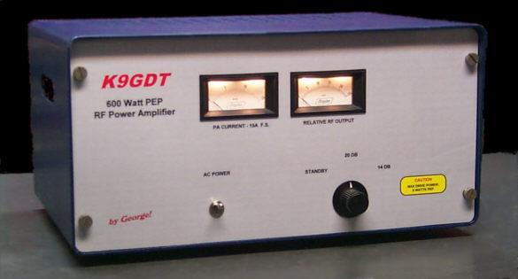
There’s an old axiom in amateur radio which states “Life’s too short for QRP.” While I generally disagree, it certainly appears to be true for 75m AM operation here in central North America, where a one watt carrier can quickly become buried in QRN & QRM. This amplifier is a mate for the QRP 75m AM Transceiver described elsewhere at this site.
The amplifier uses four Motorola MRF150 50 volt TMOS power FETs configured in push-pull/parallel and biased for class AB linear operation. This scheme yields a power gain of 20db. The 1 watt drive from the “Wheat Box” will produce a 100 watt carrier (400 watts PEP @100% modulation) with headroom to spare.
There’s little original design here. The basic 2–30MHz PA brick is straight from Motorola’s application note EB104. The power supply, low-pass output filter, control circuitry and instrumentation are mine. Still, I would describe this project as mostly an excercise in packaging.
Some amplifier highlights:
![]()

![]()
This site was created by EA3TC and built with
![]()
The End