| |
MODULE V - FUNDAMENTALS OF ELECTRONICS
RESISTORS (final page)
How does this current compare with the current for the series circuit? It's more. This
is sensible. Connecting resistors in parallel provides alternative pathways and makes it
easier for current to flow. How much current flows through each resistor? Because they
have equal values, the current divides, with 6 mA flowing through R1, and 6 mA
through R2.
To complete the picture, the voltage across R1 can be calculated as:

This is the same as the power supply voltage. The top end of R1 is connected to the
positive terminal of the battery, while the bottom end of R1 is connected to the negative
terminal of the battery. With no other components in the way, it follows that the voltage
across R1 must be 6 V. What is the voltage across R2? By the same reasoning,
this is also 6 V.
| KEY POINT: |
When components are connected in parallel, the voltage across them is the same. |
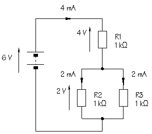
Here is a slightly more complex circuit, with both series and parallel parts:

Circuit
with series and parallel resistors
To find the overall resistance, the first step is to calculate the resistance of the
parallel elements. You already know that the combined resistance of two 1  resistors in parallel is 0.5 resistors in parallel is 0.5  , so the total resistance in the circuit is
1+0.5=1.5 , so the total resistance in the circuit is
1+0.5=1.5  . The power supply current is: . The power supply current is:

This is the current which flows through R1. How much current will flow through R2?
Since there are two equally easy pathways, 2 mA will flow through R2, and 2 mA
through R3.
The voltage across R1 is given by:

This leaves 2 V across R2 and R3, as confirmed by the calculation for R2:

Again, the sum of the voltages around the circuit is equal to the
power supply voltage.
Check through this section carefully. A clear understanding of the concepts involved
will help tremendously.
Power rating
When current flows through a resistance, electrical energy is converted into heat. This
is obvious in an electric torch where the lamp filament heats up and glows white hot. Although the result may be less evident or
imperceptible, exactly the same process of energy conversion goes on when current flows
through any electronic component.
The power output of a lamp, resistor, or other component, is defined
as the rate of change of electrical energy to heat, light, or some other form of energy.
Power is measured in watts, W, or milliwatts,
mW, and can be calculated from:
 |
where P is power.
What is the power output of a resistor when the voltage across it is 6 V, and the
current flowing through it is 100 mA?

0.6 W of heat are generated in this resistor. To prevent overheating, it must be
possible for heat to be lost, or dissipated, to the surroundings at the
same rate.
A resistor's ability to lose heat depends to a large extent upon its surface area. A
small resistor with a limited surface area cannot dissipate (=lose) heat quickly and is
likely to overheat if large currents are passed. Larger resistors dissipate heat more
effectively.
Look at the diagram below which shows resistors of different sizes:

The standard size of carbon film resistor used in most
circuits has a power rating of 0.5 W. This means that a resistor of this size can
lose heat at a maximum rate of 0.5 W. In the example above, the calculated
rate of heat loss was 0.6 W, so that a resistor with a higher power rating, 1 W
or 2 W, would be needed. Some resistors are designed to pass very large currents and are
cased in aluminium with fins to increase surface area and promote heat loss.
Input and signal processing subsystems in electronic circuits rarely
involve large currents, but power rating should be considered when circuits drive output
transducers, such as lamps, LEDs, and loudspeakers.
Free download Color Code Convertor Program.
|