Variations of Coils
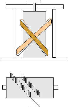
This is a Variometer, built in 1924. The coils may rotate from 0 to 180 degrees, from minimum to maximum coupling.
The lower picture shows how to build this coils.
How the winding have to be made look above. First
you build the lower coil and then above the upper.
Fix both with adhesive. Put away
the wooden Stifte and remove one or two windings between
both coils.
So you have two separated coils. The outer coil you may
fix outside. The inner coil you can turn around.
This is a standard Variometer, used from most OM's. It is easy to build but makes some problems. If the copplin is too big, the Güte Q goes rapidly down. So you have to coopel only some centimeter. The inner kapazitance is very high, that means the coil has a own resonance frequenzi ( ca. 1-2MHz ). This is the reason that the Güte Q is relative low (80-150).
Possible Parameters are :
outer diameter 150mm PVC pipe 50 cm long with 200 winding of 1,5 squaremillimeter
cupper wire ( use 3 times 1,5 NYM and split it)
inner diameter 100mm PVC pipe 35 cm long with 100 windings
so you get a coil with 3,8 mH, Q = 90, with 35pF capazitance
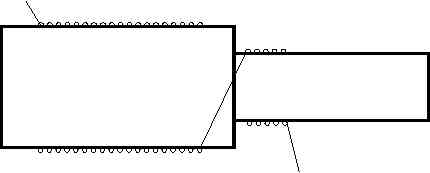
This is an example how to use two thin coils as an simple Variometer

 |
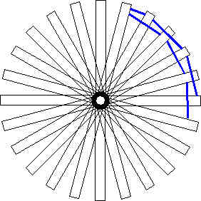
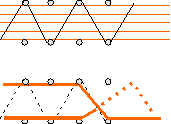
This is an example how to style the coil. With this construction
you get a low Capacity.
The first 3 turns are radial, the next is running around the wooden pins from the left to the right side like it is shown in the next picture. For construction you have to take a cylinder with pins, like shown in the upper Variometer. The number of pins you use have to be uneven. |
 |
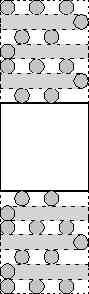
This shows how to lead the wire |
Simple coil with wodden ledges. The diameter may be 50 to 100 cm.