Modifications to the 1st IF unit
The module containing the HF preselector filters, the 1st mixer, the IF filter for the 1st IF and the 2nd mixer, is being equipped with an additional IF amplifier that raises the IF level for the FM demodulator while not drawing too much signal power from the main IF path.
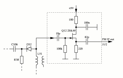
Therefore, the FET Q12 which originally isolated and amplified the TX IF for the Xverter connector as well as the connector J1 on the module are re-used. The image below shows the new amplifier circuit, which has been built in PCB-less free-wire technique and resides in the right chamber (filtered RX IF). The output of the amplifier is fed to 2 pins of J1 with a thin coax cable that previously ended at the original place of Q12.
From J1 on the RF / 1st IF unit, a thin shielded cable goes to the PC-Board of the SWR-module (From there, another cable connects to the Xverter connector on the rear side of the transceiver). The 2 pins on the SWR-module end of the cable are removed from the connector-housing, and the cable is freed out of the cable-tree so that it can reach the FM demodulator located on the upper side of the transceiver, where the LDA-unit resided. The 2 pins are inserted into the spare 2-pin housing from above.
FM-demodulator, squelch and AGC
The FM-demodulator is built onto a pin-array universal PCB that has a spare ground-plane on the component side (for better shielding). The circuit is shown in the next image below. It is mounted in place of the optional LDA-unit on the upper side of the transceiver. It is fixed with one screw into the right metal lever next to the RF unit. To be sure that no pins on the solder side of the FM board are shorted to ground, the left metal lever is bent down and isolated.
The RX IF is fed to the demodulator via a 2-pin header (P1). The remaining lines are connected via a 7-pin half IC socket (P2).
The +9V supply is taken from pin 3 on J3, the -10V are taken from pin 2 on J2 of the main unit.
The frequency of xtal X1 is the difference between 1st IF of 39.7315 MHz and the FM IF of 455 kHz. It has to be custom made for the frequency of 39.2765 MHz.
On the FSW-unit behind the front panel, base and emitter of Q3 (located near the RF-Gain potentiometer) are bridged. The AGC-signal that comes from the RF-Gain potentiometer and is present on pin 8 of P52-P18 (cable connector, not on PC board) is cut before it is splitted into one signal for the RF unit and one for the IF unit.
On the FM demodulator board, the RF-Gain signal is also used as squelch for FM. In the other modes, the signal is buffered and re-injected as AGC into RF and IF unit.
FM modulator stage
The RTTY oscillator on the bottom side of the transceiver was originally meant for FSK transmissions. For this purpose the logic level of the FSK-line was fed to Q1 which switched an additional capacitor to the XTAL oscillator at logic "1".
The oscillator signal on the 2nd IF frequency of 9.0115 MHz is mixed up to the 1nd IF, passband filtered by FI1 and finally mixed down to the transmitting frequency.
The image below shows the changes to the RTTY unit as well as the construction of the FM modulation amplifier and limiter. The xtal X1 had to be replaced by a CB xtal for 27.045 MHz TX, because the factory supplied xtal could not be calibrated that TX frequency and display matched.
The modulation AF is taken from Pin 1 of J1 on the main unit.
Modifications to speech processor and power control
Additional to the above FM modifications, some components on the main unit have been changed to achieve a better response of the speech processor, which also regulates the TX output power.
Therefore, the changes shown below were made.
The power control in AM is somewhat critical before and still after the modifications, because this mode would need a regulation of the average carrier voltage, not of the peak envelope power (PEP). The necessary switching circuitry for the loop amplifier has however not been implemented.
Conclusions
It has shown that in FM mode the VFO needs to be tuned approx. 1.0 kHz up. The FM TX oscillator has been accordingly tuned, to achieve coincidence between TX and RX. The reason for this could be a slightly mistuned frequency of the mixing xtal for the FM IF.
The image below shows the readily installed FM demobulator unit.
This page was last modified 1999/06/20 by
DL4SDC.
It can be viewed with any browser.