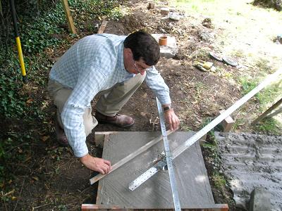
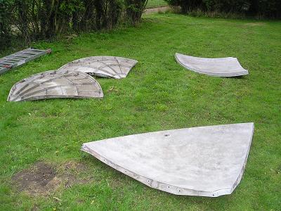
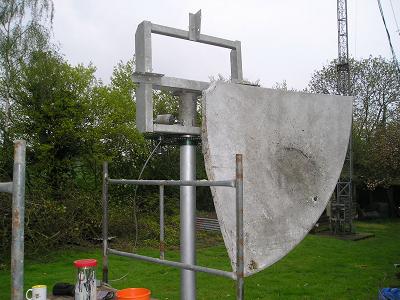
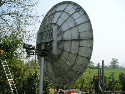
The dish is 0.4 f/D, so should feed very nicely with the existing RWST feeds that I have for 23 and 13cm - although I am tempted to move to a circular profile horn, rather than rectangular.
|
|
|
|
|
|
|
|
|
|
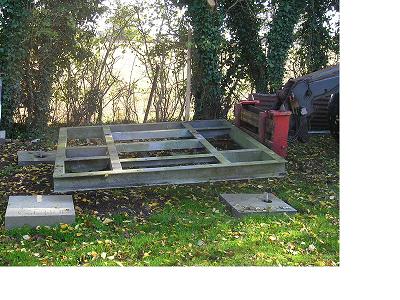
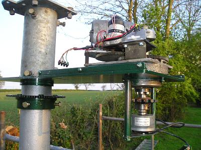
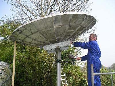
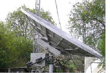
Having got the dish assembled, I now need to sort out one or two small issues with the azimuth drive - at the moment the drive sprocket is slipping on the shaft at some points - a bit of attention with a drill will ensure that the grub screws bite properly into the shaft! I've also got to get on with the control electronics now - I can drive the dish around manually, but need to get interfaced to the controller. The elevation also needs a bit of work - at the moment it can't quite be brought down to 0 degrees because a bolt head from the column fixing fouls it - shortening the bolt will be sufficient, and will allow me to reach 0 degrees for calibration purposes.
 |
 |
 |
 |
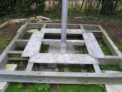
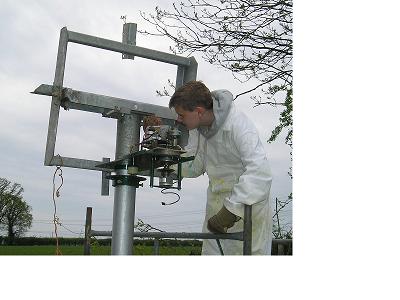
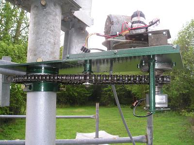
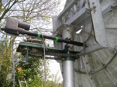
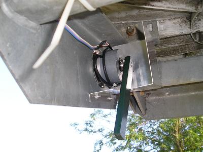
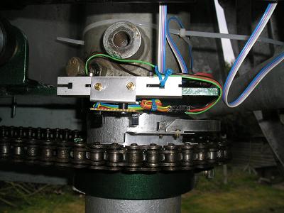
The slipping az drive has been corrected - the screws now bite into the shaft and this has cured the problem completely. The motor assembly is now covered to protect it from the weather, and the elevation jack has been wired up. I'm now expert in stripping down sat jack motors! The jack has not been used for 12 years, and refused to run in both directions so I spent a few hours sorting that out! The elevation encoder has been added, with a rain cover. Now need to fit the az limit switches and then interface the controls to the W2DRZ system.
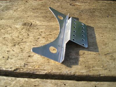
Progress update 20 May 06Not so much visible progress this week - partly due to weather, and also due to getting on with some of the electronics. Elevation relay and azimuth limit switch boards have been built - now need testing and installing - which does need an improvement in weather, and that, based on current forecasts looks like it may not be this coming week! Plates to mount the feed support spider to the dish are being made up.
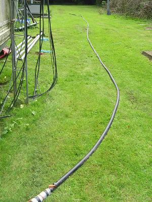
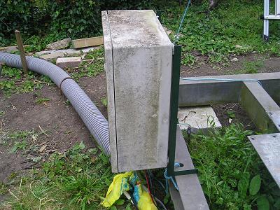
Progress update 4 June 06Not much progress in the last two weeks, due to bad weather and vacation. Have got the duct installed from shack to dish, and the Tx feeder in place. Perhaps a little premature, but as it's LDF6, then it goes in first and everything else follows! Control cable (Cat5) is also ready to be pulled in.
Progress update 11 June 06A bit more progress! The control cabinet has been installed, and mains power run out on a permanent basis via an RCD. Tx & Rx feeders, Cat5 and control cables are installed, as are PSU's for 36V and 12V for the control electronics and motors. EL drive has been re-wired, and relay control tested on the bench. Lack of light prevented testing on the dish today!
Progress update 18 June 06All control cables now installed and dressed between shack and dish, and at the dish. The control electronics for the limit switches have been tested and installed as well as the RS485 converter for the AZ and EL encoders. The limit switch opto-couplers remain to be installed.
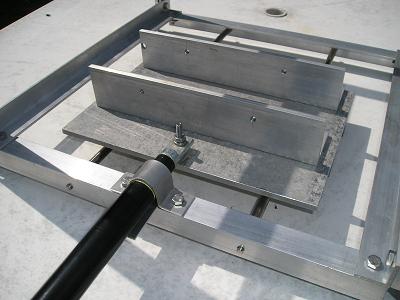
Progress update 25 June 06Limit switches installed and aligned. Mountings for the feed support frame have been attached to the dish, and the feed box is under design. The feed will be adjustable using the carriage assemblies from 2 ink-jet printers driven by a 6" sat jack.
 |
 |
 |
 |
 |
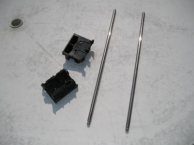 |
The weather shield has been added over the limit switches - this is also necessary to reduce the ambient light levels on the opto-switches. Installation of the shack end of the control system has begun, and will be completed in the next day or two. Design of the feedbox is completed and assembly will start in the next week. The slide bars have already been prepared by removing a shoulder at one end of each bar, allowing them to fit fully into the feed box.
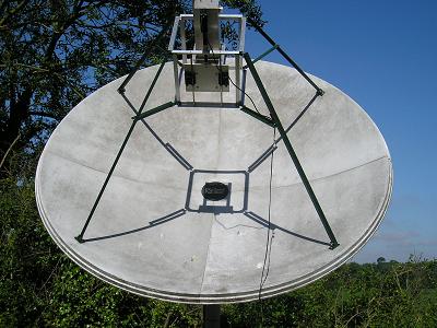
Progress update 9 July 06During the week the tracking system has been checked out and after fixing a couple of minor faults is now working. The dish has been calibrated against a compass, and a 'cross-hair' has been produced on the dish by stretching string across between the feed support mount points. By using the shadow cast by the sun on the centre of the dish I can see that the tracking is within a degree on both AZ and EL - further tests with sun noise will be made once a feed is installed. The metalwork for the feedbox is now all prepared and drilled, and assembly will take place during the next week
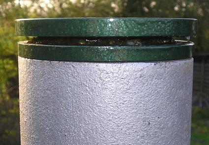
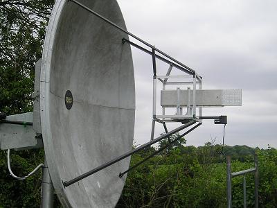
Progress update 16 July 06The feed support structure has been completed this week, and mounted onto the dish, along with the 23cm RWST feed, ready for initial sun noise testing and calibration. The motor driven feed adjustment appears to work well mechanically, although RF testing is yet to take place. Total movement is just under 15cm, which should be plenty to ensure the correct positioning of the feed phase centre at all bands above 23cm. A weather cover has been made from a surplus plastic barrel, of the type used in the food industry - microwave oven testing confirmed that the material had no effect on the passage of RF waves. Initial RF alignment and testing will take place during the next week, and maybe I will even be ready to listen for stations in the coming activity weekends......
 |
 |
 |
 |
During the week the preamp (WD5AGO with NEC 38525) has been checked - previously measured at approx 0.5d NF and with just over 20dB of gain. To prevent oscillations I had put some anti-static foam in the lid of the box. Apart from some small tweaking of the inductors (input inductor - minor change, interstage inductor - larger change) resulting in about 0.05dB improvement in NF, a major improvement was gained by replacing the foam with proper microwave absorber material - the NF dropped to less than 0.3dB! When measured with the relay and all adaptors that will be used with the feed, the complete LNA assembly comes in at around 0.45dB - thoroughly acceptable! The RWST feed was also checked for reflection coefficient, measuring 0.05 on the TX port and 0.07 on the Rx port - similar results have been seen on other samples with different connectors on the ports (7/16 and SMA). Isolation between Tx and Rx was 22dB. A second stage preamp using the G0MRF design with ATF54143 was assembled to ensure that there was no degradation due to the 20m RG213 run back to the shack. Everything was assembled onto the dish ready for testing - the feed was aligned for centre using a laser level, and the two stages of preamp attached to the support. At switch on on Saturday morning, after checking that the local beacon could be heard I tuned to the EME segment - and very quickly found G4CCH in QSO! First Signals Heard via the Moon!! Howard was not strong but was copiable in QSB. Once I got Spectran running he was about 10dB above noise on average. More signals heard this morning, so now it is time to get into the serious stuff of sun noise measurements and feed optimisation (do I need a choke ring or not?) to see if I can pick up another fraction of a dB or so. I also checked through the cables that will be used to connect to the feed on Tx and found a crushed 7/16 plug - so I need to find another plug for FSJ4 before I can complete that side of the system
Progress update 30 July 06Another one of those weeks with not so much visible progress! Have now found the 7/16 connectors to complete the Tx side of the system, and have also cracked an annoying problem I've been battling with for some time - getting audio out of the TS2000 via the packet interface (ACC2) socket. Solved it by building an interface box from scratch and ditching the one I was given! I have also picked up a couple of switching PSU's, one of which will replace both supplies currently in the control box - freeing up space and a mains socket outlet! I did make a preliminary sun noise measurement this week - approx 5dB, which is not bad for no adjustments. I need to do a bit of work to get to a state where I can make a more accurate measurement and then start adjustments to optimise the system. This will involve using the old DB6NT 1296 - 144Mhz transverter as part of a measurement system, but running with the LO at 1155MHz to bring 1292MHz out at 137MHz. The change is necessary to avoid the strong signal from GB3MHL beacon on 1296.830 MHz - it's 40dB over 9 on the dish, almost anywhere I point!
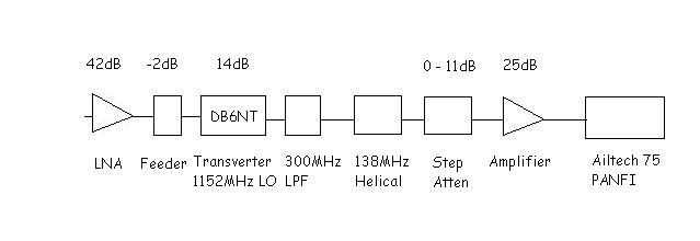
Progress update 6 Aug 06More progress this week - the moon is too low for any more listening attempts, due to tree blockage. Audio interface is now working and set up for transmit, and a makeshift radiometer has been assembled from filters and amplifiers, using my Ailtech 75 PANFI as the indicator device. The diagram below shows the system - slightly modified from last weeks thoughts, and now using an 1152MHz LO with a 138MHz IF filter, which means I am measuring broadband noise (approx 4MHz wide), centered around 1290MHz. This is sufficiently away from 1296 to reduce the feedthrough from the GB3MHL beacon to a low level signal outside the main passband of the noise receiver. The step attenuator has 1dB and 0.1dB steps allowing a fairly precise measurement to be made. Unfortunately, just as I was about to start making measurements, the PANFI developed a PSU fault and is tripping out the mains supply to the shack! However, adding a further 30dB amplifier in the system enabled me to use the HP435A Power Meter to measure the system noise. An initial measurement late today indicated 6.3dB Sun/cold sky after optimising the feed. Interestingly, the position for maximum sun noise is approx 1.5cm forward (ie closer to the dish) than the calculated position. Further measurements need to be made with the sun higher in the sky. Later in the week the moon does get sufficiently high for me to start using it again.
OK - well it's been a bit more than a week since the last update, and a lot has happened! As the moon has got more usable I've had my first JT65C QSO with G4CCH for #1, followed by a CW QSO the next morning. On 16 Aug during the morning I worked K2UYH, WA6PY, G3LTF, F2TU, SM6CKU, W5LUA and OK1DFC bringing me up to initial#8 - all on CW! The DB6NT PA is now remotely mounted ina plastic cabinet at the base of the dish, but I am not getting the full power out of it - only seeing about 150W for 0.5W in. No update next week as I'm off to EME 2006 - but hoping to get a few more initials in first!
The 2m low power station antenna has been removed, pending re-mounting on the dish at some later stage.
G4HUP 2m Initials. DL4MUP 23cm Initials. Click here for G4HUP and DL4MUP EME history.