D: Eine einfacher Rogerbeep. Beim Einbau müssen keine Leitungen im Gerät unterbrochen werden.
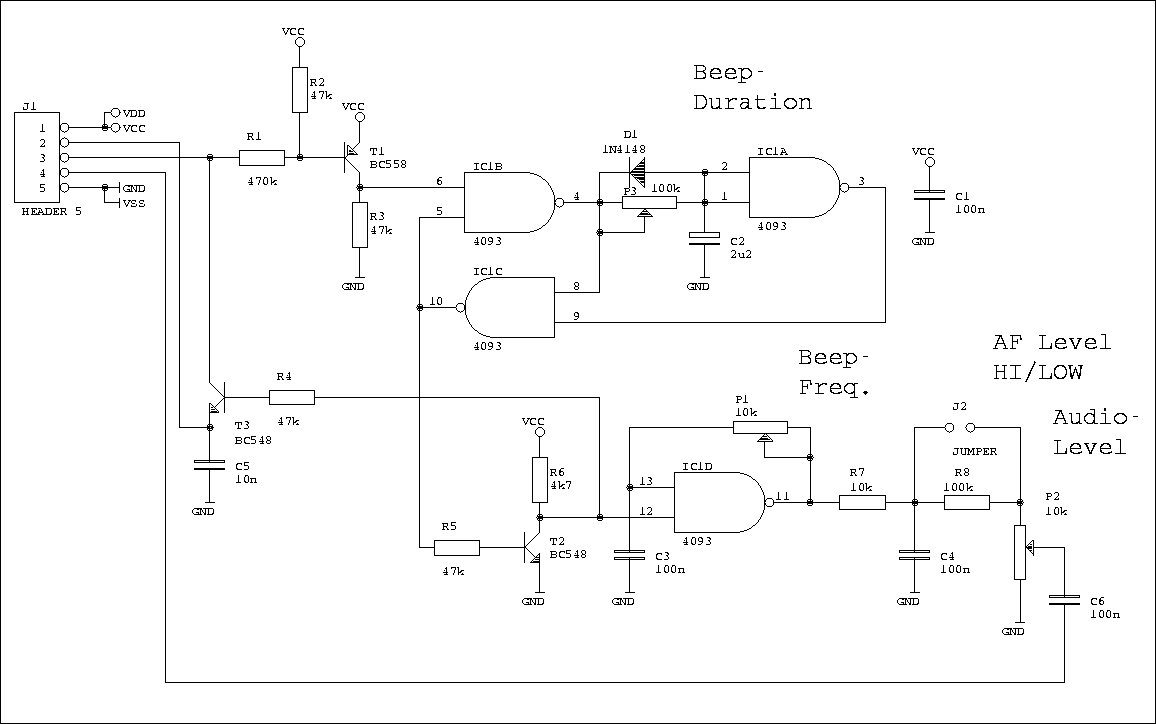
An J1-Pin2 wird die PTT z.B. vom Mikrofon kommend angeschlossen. Dort muß ein aktiv-low Signal vorhanden sein. Mit dieser Leitung wird nachher beim "Piep" auch das Gerät auf Sendung gehalten. Alternativ kann der Eingang auch mit einem positiven Signal versorgt werden, dann wird T1 nicht bestückt und an dessen Emmitter eingespeist.
Um IC1A ist ein Zeitglied aufgebaut, das über P3 regelbar die Dauer des Tons bestimmt. Während eines Tones wird der Trigger für das Zeitglied über IC1C und IC1B gesperrt. Der mit P1 regelbare Oszillator um IC1D piept wärend dieser Zeit. J1-Pin4 wird an die Mikrofonleitung angekoppelt. J1-Pin3 muß zum Aktivieren der Schaltung auf Ground gelegt werden.
Die Schaltung sollte bei Spannung zwischen 5V und 15V arbeiten. Die Spannung hat aber geringen Einfluß auf Tondauer und Tonhöhe.
J1-Pin2 is connected to the PTT from e.g. the microphone. There must be an active-low signal provided. Also this wire is later used to hold the TRX on TX during the "beep". Alternativly an active-high signal can be fed when T1 is not inserted at its emmiter.
IC1A builts a time delay circuit. P3 is used to vary the duration of the tone. During the "beep" IC1C and IC1B prevent the time delay to be retriggered. The variable oscillator around IC1D/P1 produces the beep. J1-Pin4 is connected to the microphone input. J1-Pin3 must be grounded to activate the roger beep.
The circuit should work with a 5V to 12V supply. The voltage has a low influence to tone duration and tone frequency.
Schematic:

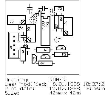
Picture: Place Plan (click on the image to get a Postscript file)

Picture: Solder Side (click on the image to get a Postscript file) (ready PCBs are available on request)
![[HOME]](green.gif) Last updated 980212 08:00 by DL4MEA
Last updated 980212 08:00 by DL4MEA