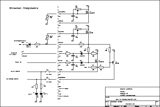
Als weiterer Inverter sorgt T2 für die Betriebsspannung der Relais des Vorverstärkers. Der Vorverstärker selbst bleibt immer an Spannung angeschlossen, um den FET (MGF1302) besser zu schützen.
T4 dient zur Ansteuerung eines Lüfters. Bei Erreichen der Schaltschwelle wird der Lüfter mit Spannung versorgt und kühlt die PA. P1 wird so eingestellt, daß der Lüfter bei Raumtemperatur sicher abschaltet.
T3 dient zur Übertemperaturabschaltung. Beim Auftreten von Übertemperatur wird das Gate von T1 und die Basis von T2 so stark nach +12V gezogen, daß diese nicht mehr schalten können. P2 wird so eingestellt, daß die PA bei starker Erwärmung nicht mehr arbeitet.
Diese Schaltung ist auf einer Lochrasterplatine aufgebaut.
E: This circuit is dedicated to control the RF switching unit. With D1 and D2 two active-low inputs from the RF-VOX and a PTT input are ORed. T1 is a P-channel power MOSFET and provides +12V during transmit with a low impedance. This voltage is feed to the idle power of the PA stage and the PA-relays via an external switch.
A further inverting transistor T2 provides the power for the preamp relays. The preamp itself is continously powered for a better protection of the FET (MGF1302).
T4 is used to power a blower. If its gate voltage is reached the blower is powered and the PA stage is cooled. P1 is set to a value where the blower does not work on room temperature.
T3 is used for an overtemperature protection. If there is overtemperature the gate of T1 and the basis of T2 are blocked to +12V so that they cannot switch any more. P2 is set to a value where the blocking happens at high temperature.
This circuit is built on a wire-wrap-board.
Last time changes (and so it works):
Picture: Schematic of the easy PA switch (click on the image to view (and save) a high resolution GIF picture):