When I got my FT847 mid of May 1998, I started to think about a test series, which would verify this amazing tranceiver to my current radios (IC251, IC475) . Since I am not an active operator of shortwave, I cannot and will not do any work for these bands.
If you are looking for modifications of the radio, you should have a
look at this page: The FT-847
Home Page
Comments:
In my opinion the RIT (Yaesu calls it clarifier) is unusable compared to my older IC475. The FT847's RIT functions are ON/OFF and tuning. It clears to zero if switched off and you turn the main tuning knob. There is no sepearate display for the RIT value, and no RIT-CLEAR button. So in my opinion two very useful options are very missing:
Measurements done:
The transmitter is not of interest for me. It worth if it delivers 49.9W or exciting 50.1W, its enought and the rest is the job of my amplifiers.
I was mostly interested in the receive performance. So I coupled a weak beacon into both radios at the same time, and recorded the received signal parallel on left and right channel of the sound card with 22k samples/second. I then took a 10sec sample of both channels and analized it with COOLEDIT. Previous verifications of COOLEDIT and FFTDSP showed, that the signal-to-noise ratio, which is displayed in both, is very similar.
The tests were done on 432MHz using a beacon over a 500km path. Since there are always airplane reflections and QSB, I made the verifications with the IC475 to have a reference signal. My preamp is around 0.4dB to 0.5dB NF and provides much enougth gain to drive the S-meter into S3-S5 range.
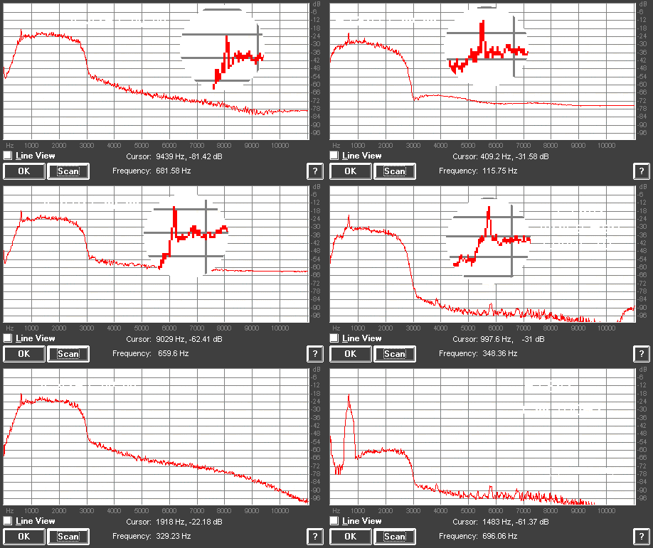
First test was done using both radios in CW-wide. You can see the beacon
is there with around 6dB S/N on both radios.
Second test was done using the noise reduction (NR) of the FT847 set
to 10. The beacon is some 3dB more above the noise.
Third these was done using DSP bandwidth 100Hz on the FT847. Look carefully
to the picture. I must overwork it to see just the around 1kHz around the
signal,, and not the complete audio bandwith. If you look carefully, you
can see the around 6dB improvement against the IC475's S/N.
I verified these S/N impressions with FFTDSP, and came to closely the same results. Using 25Hz bandwidth even improves the results of S/N, but since each picture takes 4min calculation time on my current 486/133, its much work to do more pictures, but they will come up.

Additionally, I want to verify the code readablity on the weak signals
to see what is about ringing and so on, but this is currently not done.
Its a work for the future...
Moonbounce Echo Tests:
At July, 1st, 1998, I noticed that I get fine echos from the moon. These were around 10-15dB over the noise and so I tried to record some signals to verify the performance of the FT847's receiver.
The test setup was:
The conditions seemed to be very stable at that time, there was nearly no QSB or fading. This is why I did not run double receivers.
NOTE: The Noise Reduction (NR) function sometimes runs into an unusable working mode when the receiver gets the strong TX signal. Just switching the NR off and on recovers the tremendeous operation of the noise reduction.
All of the pictures and recordings were made with AF9Y's FFTDSP software. I guess below those working EME this is common known, and most of you will know what a signal sounds when they see the bar drawn on the screen. The recorded WAV files are also present.
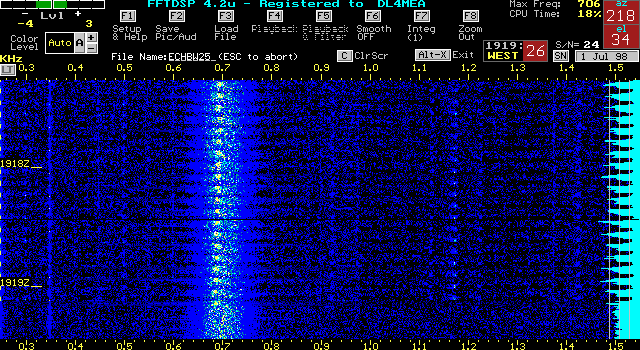
First test: Just echos while CW-Bandwidth filtered to 25Hz. At the bottom
you see a short time with just the noise of the background. There is a
spurious of the TX signal at around 1170Hz. The moon was leaving and so
you see that the doppler shift at that moment was around 470Hz.
Result: In my opinion the 25Hz filter works
good, but is nearly too narrow to operate with. My echos sounded best when
read with the 100Hz filter.

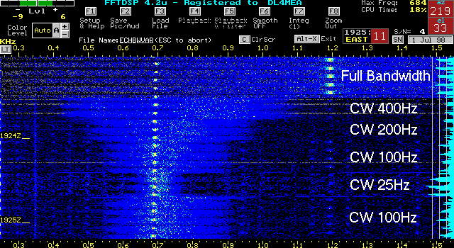
Second test: Echos with varying bandwith
Result:
If you listen to the recording, you will possibly agree that 100Hz is the
best bandwidth

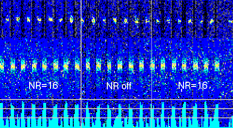
Third test: Noise Reduction
Result:
I zoomed the display on the bottom, you may also notice that the S/N is
some few dB better if Noise Reduction is on. Its very convenient to use
the NR when scanning the band, you can have full bandwidth. That confirms
also what I found out when I used K6STI's DSP-Blaster noise reduction mode.
Zoomed Picture:
( I am shure that what you see is really due to the Noise Reduction, not because of fading. The conditions were very stable during the time of measurement)
