The Development of the FPGA Based ADS-B Receiver and Decoder
(C) Günter Köllner, DL4MEA 03/2011
This page describes the development of the final product Mode-S-Beast, which you can find here.
Scope
/ Überblick:
E:This
page introduces a FPGA based ADS-B decoder, which includes also
one
improved RF receiver, based on the miniADSB concept. There is an option
for additional 3 external
receivers dedicated to high sophisticated antenna experiments like
antenna
segmentation or high gain directional antennas towards areas of special
interest, for example the airport which cannot be received with the
omni directional antenna.
Due to the use of an FPGA and not a microcontroller like PIC or Atmel
there are no bottlenecks in performance since
all tasks are running in parallel. The standard interface towards the
PC is USB-serial, optionally a Lantronix Xport can be equipped on the
bottom side, as well as a BTM-222 bluetooth module.
For own experiments or extensions, there is also on the bottom side a
place given where an
Atmel ATMEGA can be equipped. All interesting
pins of the Atmel are accessible via pin headers, so this board can be
used in any user defined PCB as a piggy pack module. The Atmel in this
case also has access to all external serial interfaces.
The dedicated GUI software for this Receiver/Decoder is COAA
PlanePlotter,
however, since the output AVR format is not encrypted, any other GUI
software or self developed software can make use of this unit, too.
D: Hier
stelle ich einen FPGA
basierenden ADS-B-Decoder inklusive eines Empfängers, der auf
dem miniADSB Konzept aufbaut, vor.
Optional
können bis zu 3 externe ADS-B-Empfänger angeschlossen
werden,
um zum Beispiel komplexere Antennenstrukturen (segmentierte Antennen)
oder eine Antenne zu einem Punkt von speziellem Interesse,
z.B. außerhalb der Reichweite der
Rundempfangsantenne zu
unterstützen. Durch die Verwendung eines FPGA anstelle eines
Mikrocontrollers gibt es keine Performanceengpässe, alle
Prozesse
laufen ständig und vollständig parallel.
Für eigene Experimente oder Erweiterungen gibt es auf der
Rückseite einen Einbauplatz für einen Atmel ATMEGA.
Alle
interessanten Pins des Atmel sind über Pinleisten
verfügbar.
In diesem Fall kann der Empfänger auf ein eigenentwickeltes
Board
aufgesteckt werden. Die Atmel-CPU kann alle drei seriellen Interfaces
benutzen und erhält die ADS-B-Daten ebenfalls über
seriielles
Interface.
Die auf dieses Board zugeschnittene GUI-Software ist COAA
PlanePlotter, aufgrund des offenen und bekannten
"AVR"-Formats können aber auch andere Programme verwendet
werden.
Im weiteren Verlauf der Seite verwende ich englische Sprache, da dieses
Projekt von weltweitem Interesse ist. Eine Übersetzung ist am
einfachsten mit Google-Translator möglich:
Ins Deutsche
Francois
17.01.2011:
The development
phase of this decoder was closed, the final description is later on
this web page. The project was also named "ADS-B Beast", because it
really is a beast when running. It provides so many frames that the PC
behind quickly becomes overloaded. If ever you track the data flow from
it on a terminal, you will see incredibly much frames per second.
Note:
- Most pictures are shown as icons only, so if you click on
them
you will get them in original resolution.
- The range circles on the graphics are drawn up to 200nm
(about 360km), with 25nm stepping.
- All examples shown here if not otherwise noted were
recorded using the omnidirectional antenna shown in my PICADSB
article.
Main Differences to the existing solutions: Drastically higher frame rate
and by 75nm increased
reception range
There are two main differences to the existing solutions: Number of
received frames per second, and reception range. At the current time
this can only be given for my own home location, but I can clearly say
that there are some challenges:
- I live close to Munich airport, which has two runways and
so many planes.
- The glide path of runway 28L is just 2km south from me, so
there
are many planes just in front of my antenna. Sometimes planes fly very
close above our house at a height of 400m, as you can see in this
picture.
My ground level is 1500ft.
Due to this I quickly discovered the so called "doughnut effect" when
starting with ADS-B reception and found a way how to overcome it.
- My location is free of any blockage into any direction. You
can
recognize the first big blockage to the west-north-west caused by the
Schwaebische Alp in around 100nm distance, as well a very sharp one to
nearly strict north caused by my main antenna mast.
Number
of received frames
per second:
Any microcontroller solution lacks of parallel processing
capability.
Many tasks have to be done in a sequence, one after the other. The
clock rate of them mostly does not even allow to calculate CRC while
receiving the bits of the 1MBit/sec ADS-B signal. Even simple serial
transmission cannot be done in parallel, so for example while PICADSB
is transmitting a decoded frame to the PC on the serial interface, it
cannot receive the next
frame at the same time in parallel. This must be even worse if the USB
connection is
handled by the PIC like in Sprut's solution, because USB requires even
more processing ressources, but I have not proven personally.
Using and FPGA, these bottlenecks can all be overcome. All tasks are
running in parallel. Immediately after a frame was finished, the
receiver is armed for the next one, while the frame is put into a FIFO
and transfered to the serial transmitting unit. Of course, the CRC
calculation was already done during the reception of the bits
themselves.
Given as numbers, running with the same ADS-B analogue signal, at the
same time I can see:
|
PICADSB |
FPGA-Decoder |
| DF-17
frames only |
15 |
100 |
| all
frames |
100 |
300-500 |
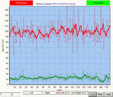 |
With
Andy Kruse's Mode-S compare tool, this can be displayed grafically in
an impressive way.
The recording was made during a weekday's afternoon (26.10.2010) with
moderate air traffic.
The relationship is linear, so if the PIC shows 20 frames/sec, the FGPA
decoder shows around 130-140 frames/sec.
Both receivers were connected to the same antenna using a 6dB splitter.
|
Why
does one need this frame rate?
One of the problems that must be understood here is that Planeplotter
has a very long integration time. That means the time while it just
draws a plane straight forward from the last received position
according to its known speed and direction. So you might not even
notice that you receive just a few information from an object on your
screen.
These things drastically change and become quite ugly when you have
planes circling around in your observed air space, as you may notice in
the pictures below.
|
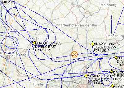
Low frame rate (all µC
solutions)
Quite often the planes were just drawn straight forward while in
reality they were turning. Just with the next received frame they were
brought back to their current course. |
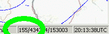
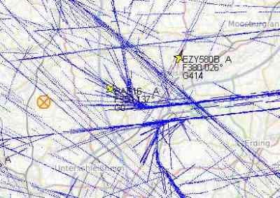
High frame rate - FPGA decoder
Due to the high frame rate, mostly 2 packets per second from the planes
shown, smooth circles are drawn. The full picture will show you this in
an even wider range, notice that at this time I had in total 155 planes
in my range, and quite a lot of them were circling around. The picture
was taken after Munich airport was closed due to a heavy thunderstorm. |
2
Minute Plots
Another good test is to let both decoders run against each
other for
just 2 minutes at the same time (or at least directly after each
other). Following pictures were taken on a sunday evening with less
traffic all around.
|
PICADSB decoder
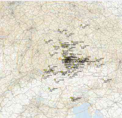
The picture shows 80 planes and 1464 frames having been used to create
it.
|
FPGA decoder
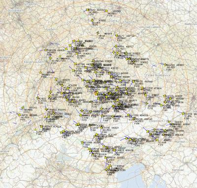
Using the FPGA-Decoder, we got 153 planes (nearly twice as much) and a
total of 8042 (nearly 6 times more) ADS-B frames. It is also clearly
visible that there are significantly more planes from far distance.
|
Reception
range:
Next, a microcontroller is just able to sample the input
signal once
per bit. So in case of a noisy (received from far distance) signal, and
if there is just a noise pulse at the time of sampling, it will read
false. ADS-B
signals unfortunately do not transmit power for logic "0", so always
random noise is received in these phases.
Due to the high speed of the FPGA, it can do oversampling. Currently I
am using 10 Megasamples per second. So there are 5 samples availble
that
decide if a bit (of the manchester signal) has to be seen as "1" or "0"
. This drastically
improves the reception of weak signals.
This can be shown when running the receiver for a night, mostly between
23:00 and 05:00 local time. In other times there is so much local
traffic that distant planes are anyway blocked by the few locals, since
in ADS-B we do not have any collission detection.
PICADSB
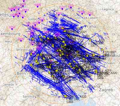
The recption range is up to around 150nm.
(Note the blockage due to the Schwäbische Alp towards
West-North-West and the sharp blockage towards 350° due to my
ham
radio antenna mast.)
|
FPGA-ADSB
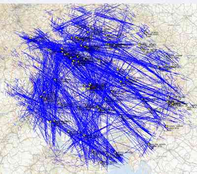
With the FPGA decoder, the reception range is extended up to about
225nm.
|
Overall Feature List:
- One improved miniADSB receiver is included on the PCB, up
to 3 external miniADSB are supported. Double frames are filtered
internally.
- FPGA based decoding allows signal oversampling and does not
impact any bottlenecks
- Noise surpression: With a second algorithm running in
parallel, especially for far distant planes up to 20% more
frames
are decoded.
- Standard interface towards the PC is USB serial, it creates
a COM port on the PC with 1MBit/sec.
- Optionally a BTM-222 bluetooth module or a Lantronix Xport
can be equipped to the bottom side.
- ATMEL support: On the bottom, you can solder an Atmel
ATMEGA
processor for own extensions. There are two pin headers which allow
access to all pins of the AVR. The AVR also has access to all serial
interfaces. Ideas here are further processing of the frames,
local LCD display, Web server, whatever you like.
- Power supply is via USB port, but external 5V/100mA (expect
more when using Xport or Bluetooth) can be applied separately.
- Improved miniADSB receiver with better noise figure and
flattened passband.
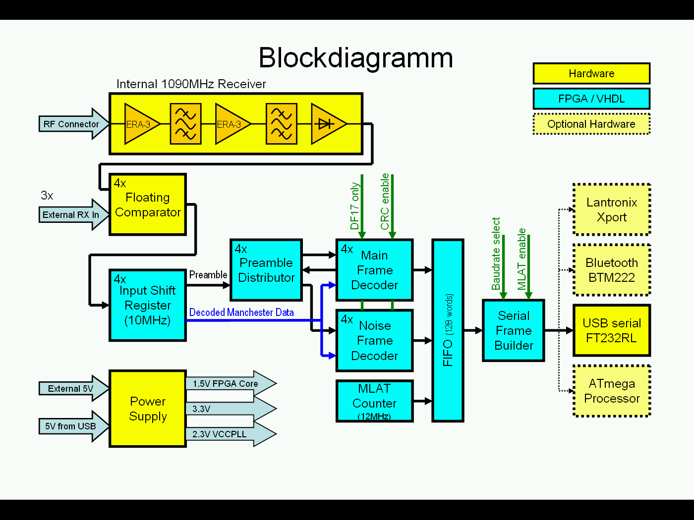
Block Diagram:
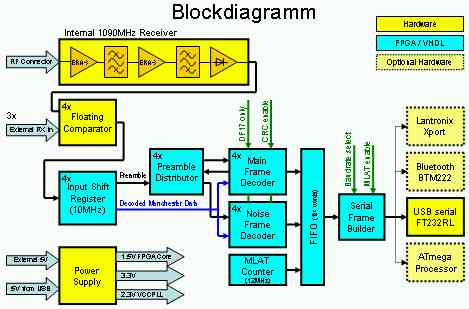
OBSOLETE!
The final product does use two MAX1192 AD converters running with
16MSamples/sec in order to support 4 RX channels.
Availability (17.01.2001):
10 units were built. 9 of them were supplied to people all around
Europe. Steps are ongoing to provide this board as a
professionally equipped kit, which means that you have to
solder
just the few non-SMD parts (LEDs, USB-Connector, RF-Connector, external
miniADSB connector)
Links:
ADS-B
Decoder PCB for Betrand Velle's PICADSB project
ADS-B Telegram Format
MiniADSB Receiver and Forum
RxControl
web page by Bertrand Velle, and blog
in french (translated
to english by google)
2 possible GUIs available: COAA
PlanePlotter or Jetvision's Globe-S
FT232RL Serial to USB converter and driver
Antenna
that I am using but with only quarter wavelength radials (see also FAQ
section)
A possible transmitter,
intended for use on ultralight planes.
Improved miniADSB receiver
Even when the miniADSB is a very
neat and perfectly working unit, there are two main issues:
- The amplifier is behind the first filter. This means that
the
filter's attenuation totally adds to the noise figure of the receiver
- The straight forward design of the devices means that they
are
not matched to each other and the optimum passpand shape is not reached
A good friend, Luis Cupido, CT1DMK, has analyzed the receiver
using HFSS and improved the design. The former BGM1013 was removed and
replaced by two ERA-3 monolitic amplifiers. These two devices still
ensure that a high IP3 is reached, because sitting nearly straight
after the antenna the first device will see a bunch of other signals,
like 900MHz GSM and DVB-T.
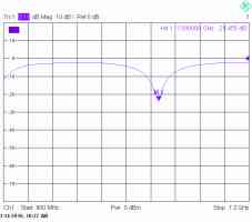
miniADSB Passband (simulated)
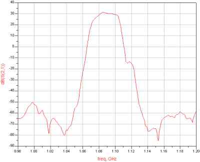
|
improved miniADSB passband
(simulated)
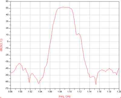
|
tbd insert real measurements
4 Receiver Concepts:
Mainly there are two ideas behind
the idea of
supporting up to 4 receivers. Whilst the basic circuit is a high
performance single channel receiver for single antenna use, with up to
4 receivers in total there are a number of new ideas possible:
Antenna
segmentation:
ADS-B transmissions are non-coordinated transmissions
without any
check if the channel is busy or not. Imagine there are two planes with
equal strength in just opposite direction to your location. In case
that they are transmitting at the same time, the signals will destroy
each other resulting in no frame reception at all.
If you would take the chance of directional antennas, the surrounding
area can be split into up to 4 independant segments. Now only those
transmissions will intercept each other which are equal strong or
stronger on each antenna.
High gain antenna
towards areas of special interest:
Another idea why several input channels are
useful is the
use of a high gain antenna towards any area of special interest that is
not covered by your omni directional antenna. For example, if your omni
does just not display the airfield in 150nm distance, or whatever else,
you now may add a separate receiver with a directional antenna without
loosing the round about coverage through your omni antenna. The signals
simply add to each other. I've for example seen such a usability in
Emden (north Germany), where it just was not possible to receive air
traffic over London, UK, but expecting this would be possible with a
high gain antenna towards London.
DIP
switch settings:
| Baudrate |
SW1 |
SW2 |
| 1
MBit/sec |
open |
don't
care |
| 921600 |
on |
open |
| 115200
Bit/sec |
on
|
on |
| Transparent
Mode |
SW3 |
| only
known data formats with CRC |
open |
all
frames pass
(unit #1-4 also: no CRC check) |
on |
| DF17
only |
SW4 |
| all
known frame data formats |
open |
| receive
only DF17 |
on |
| MLAT
enable |
SW5 |
| no
MLAT information output |
open |
| pass
MLAT information to PC |
on |
Unit #1-4:
| DF4/´DF5
enable (temporary) |
SW6 |
| decode
DF4/5 regularily |
open |
| surpress
DF4/5 |
on |
Unit #5 and later:
| CRC
disable |
SW6 |
| do
CRC check on DF17 and DF11 |
open |
| no
CRC check at all |
on |
Units with ADC (also #5 and
later):
| DF0/4/5
disable |
SW7 |
| decode
DF0/DF4/DF5 |
open |
| no
CRC check at all |
on |
Units #10
| RTS HW Handshake |
SW8 |
| ignore RTS signalling |
open |
| RTS HW handshake enabled |
on |
The Potentiometer Alignment... and Consequences
Some basics:
When I started working for ADS-B a simple comparator was used in all
non commercial designs. Due to my special location (see above and the PICADSB
weg page) I quickly found out that these comparators either display far
distant planes loosing those nearby, or loose sensitivity in case that
the comparator level is aligned to detect nearby planes. First is known
as "doughnut effect", since your overall coverage looks like a
doughnut, a ring with a hole in the middle. Because I did not want to
live with this, I found the solution of a quick adjustment of the
comparator level, done with a simply asymetric RC time stage.
Using this comparator for quite a while in the PIC decoder, I found
that there are still two optimums: One for highest frame rate, one for
maximum sensitivity (maximum
sensitivity
means widest coverage and also means maximum number of planes shown
up in Planeplotter). With the low frame rate of the PIC I was
not
able to clearly see the total effect of this.
This functional block again was implemented in the FPGA decoder because
it was no time to develop a totally new solution.
  |
In
the first
picture, the comparator is aligned for maximum sensitivity at the
beginning. Simply turning the potentiometer half a turn doubled the
frame rate.
In the 2nd picture you can see that later optimizing even rose it to
150 frames/sec.
(The legend of the picture is wrong!) |
This all does not mean that with an alignment to maximum sensitivity
local planes are lost, it is just that the maximum
possible frame
rate reached is not reached using a comparator that is aligned
for maximum sensitivity.
Speaking in distance, about the last 50nm are lost.
There are some ideas why this is the case, most probably the AD8313
still suffers from a high level recovery time. It could be that using a
schottky diode in the RC stage might give some improvement, also it
might be that a smaller capacitor would give some benefit. Actually
these are no professional solutions, so I am working for a totally
different one inside of the FPGA.
Intermediate
solution:
Since the FPGA board has 4 independant channels but only one internal
receiver, I simply drive two comparator stages from the internal
receiver. One comparator stage is aligned to maximum frame rate, one
for maximum sensitivity. They both are added in the FPGA. Switching on
and off the maximum sensitivity stage I saw that this adds about 10% to
the frame rate of the maximum frame rate stage.
Poti alignment:
Maximum frame rate
can easily be adjusted using Andy's tool as shown above. I am normally
using potentiometer #2 for this purpose.
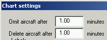
For maximum sensitivity
use Planeplotter, open the menu "Options" -> "Chart" ->
"Options"
and set both values to 1 minute. Then adjust the potentiometer so that
a maximum number of planes is displayed. Between changes, always wait
around 15-20 seconds in order to become stable.
Start turning the potentiometer with 90° steps, later you can
do some fine adjustment with 45° steps.
Those who have got a beast with two comparators (units including #3 and
afterwards) simply do the maximum frame rate adjustment using the
potentiometer numbered "2" and the maximum sensitivity adjustment using
potentiometer #1.
Summary of this development (17.01.2011):
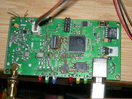
The ADS-B Beast with manually wired AD converter (bottom middle) and
manually added DIP switch |
The ADS-B Beast running with two receivers: One antenna connected to
the internal receiver and one miniADSB connected externally |
I have now finished the evaluation of this ADS-B decoder. While the
first generation, described above, was still using the floating
comparator circuit that was also successfully used at the PICADSB, the
PCB had already foreseen an MAX1192 AD converter. Within this high
performance decoder, the comparators have shown some big issues:
- They needed alignment at all, the circuit was not alignment
free, it even required re-alignment when connecting a preamp
- The alignment was possible for either highest frame rate or
for highest sensitivity
- There was no chance for higher sophisticated algorithms in
order to decode frames
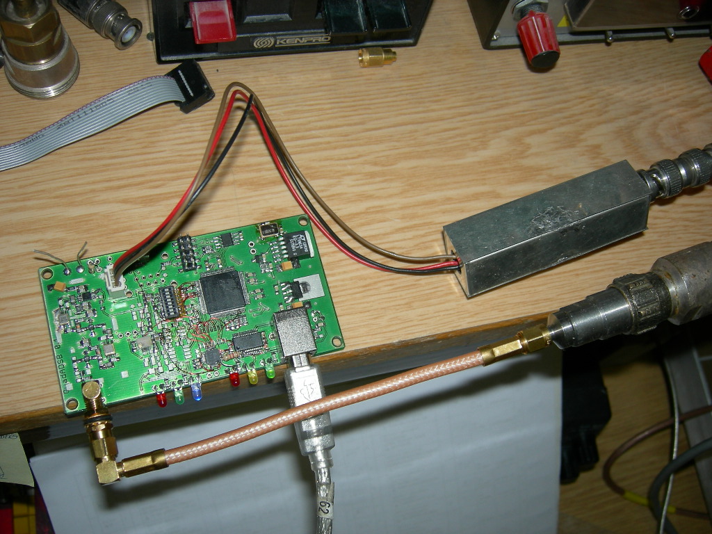
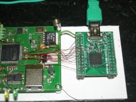
Due to those, I
found it quite necessary to proceed with the AD
converter. I quickly got it running in a basic mode, just replacing the
funcionality of the
comparator section by VHDL code. Then I made a unit that allows me to
capture the ADC values towards the PC (this is 16MByte/second). See
photo on the right side.
With the captured data I was able to trace the decoding algorithm
offline in ModelSim, and to look for the reasons why some frames were
not decoded. Also, I was able to verify the quality of the different
decoding
algorithms on equal input data.
For example, I discovered quickyl that my algorithm is able to mask DME
pulses as long as the Mode-S signal is still visible on top of it. |
 |
Bluetooth-Interface:
Interfacing the unit to the PC is done using USB as a
standard.
One unit was built with an additional Bluetooth interface. I recognized
about 10% degradation in the frame
rate with Bluetooth operating, which is quite satisfying. At the final
PCB
I did some more steps in order to prevent the RX from becoming spoiled
by the transmitter.
Ethernet-Interface:
One unit was built using the Lantronix Xport as an
interface
towards Ethernet successfully. Again here I had to match some
constraints of Planeplotter, at most the use of the CPR (COM port
replacement) of Lantronix which introduces a virtual COM port. A direct
UDP interface towards Planeplotter is not a problem and surely planned
for the final release.
Performance:
I did a verification against other high performance
receivers (not based on PIC, Atmel or so...) and it
showed an performance increase of about 25%-40%. At the moment I do not
want to present the comparison here, since there is still one
verification at a different set-up that does not match to my data.

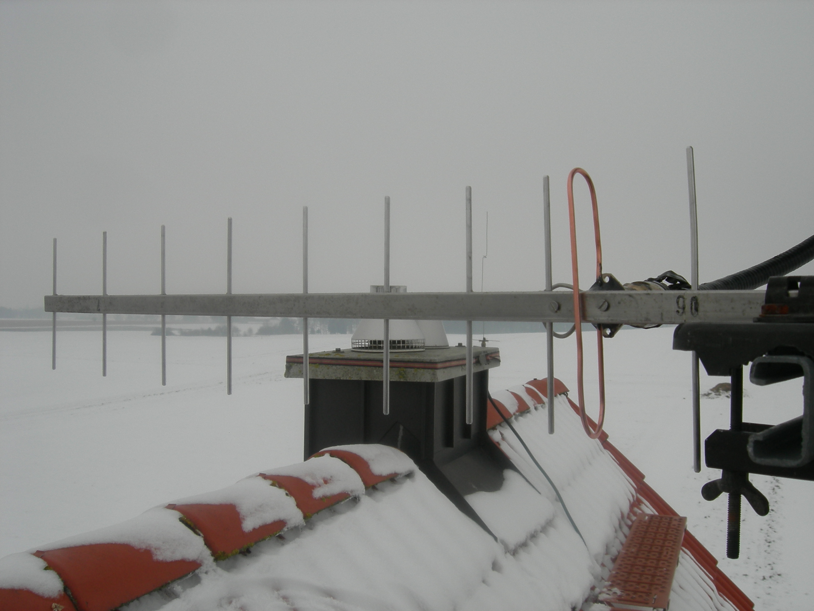
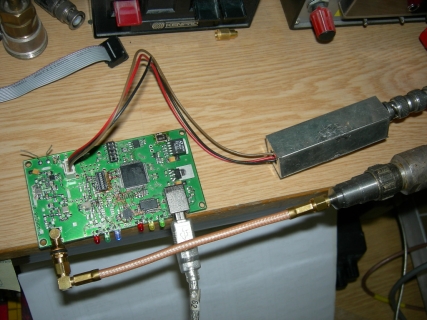
When having a local
inversion, I
found that there is significantly
ground traffic ongoing that I would be able to see on the 30miles
distant Munich airport. So
therefore I built a simple 10ele yagi and installed it towards the
airport. (In the background, wired to the chimney, you can find my
G7RGQ omni antenna)
|
The signal is received with a miniADSB receiver and fed into the 2nd
decoder channel of the FPGA Beast. Immediately I go the
ground
traffic from the airport. (Reason why some are off the runway is that they are transmitting different than real GPS data) |
This is an overnight capture. The beam of the yagi towards
East-South-East is clearly visible. The maximum distance is somewhat
over 350nm. This is again the idea to segement the reception around an
observer with several high gain antennas like AMOS or double quads and
so reach this range in all directions. |
On Saturday, 15.01.2011, Planeplotter showed my 220 planes in my range.
I made a video about this situation and have put it to Youtube
.
In the video you will see
- The FPGA Beast Version 0.1 with 2 receivers connected (as
shown in the pictures above)
- Watching the yellow USB transfer LED you will notice that
it sometimes is off for a while. At
that time Planeplotter was running on a 600MHz laptop,
which had far oo
less performance for getting all the USB protocol done. Additionally I
am accessing it with remote desktop. Its processor load is normally at
60% or higher. So unfortunately about
10-15% of frames is lost here. In order to get the data rate down at
all I had disabled DF0, DF4 and DF5 frames from decoding anyway.
- Planeplotter is displaying a tota of 227 planes.
Planeplotters
message rate meter is showing around 600 frames per second. That is
after they had been CRC checked. But as said, there is some loss due to
the USB interface, from a later occurence of about the same number of
planes I estimate it was about 750-800 in reality.
- There is a Tool "ModeSCompare" from jetvision.de that plots
the
number of DF11 and DF17 frames, which continously was around 295 per
second. In the data format column mode of ModeSCompare you will notice
that DF0/4/5 were really off, and the raw data rate was around 1000
messages per second.
Meanwhile (21.01.2011), I implemented the optional RTS handshake,
so if the PC application supports RTS/CTS hardware handshake, the loss
issue from the video is nearly solved by the FPGAs internal FIFO buffer
which can hold up to 128 (later version 512) frames. I am now reaching
up to 700 frames indicated by Planeplotter meter instead of previous
rarely 350-450.
The effect of the two antennas can also be displayed by monitoring the frame rate. The graphic on the left shows
- G7RGQ omni antenna plus 10ele yagi
- only Yagi antenna
- only G7RGQ omni antenna
There is a short peak between 2. and 3. which comes from the short time when during the swap both antennas were again connected.
Note that according to their CRC (or, last 24 bits in those frames that
don't have a CRC), frames received simultaneously on both channels are
detected and only one forwarded. If not so, you would see 380 frames
with both antennas anyway.
|
 |
F5ANN,
who has built with two AMOS antennas a reception system as I have designed the multi channel receiver for, is
showing his results with a 2 channel receiver from the first series on his
web page.
Bottlenecks /
Known Issues:
- The receiver/decoder is designed for use in a standard
environment and does not consider beeing operated close to strong RF
sources like Radar, GSM or TV transmitters. Also be always aware that
reflections are deadly for the Mode-S signal, which is the case
especially when watching ground traffic.
- I have built 10 and distributed 8 among europe in order to get
some experience, until now there was no severe failure comment neither
any severe problem..
Globe-S GUI (20.01.2011):
Besides COAA
PlanePlotter, Jetvision's Globe-S will soon become available. While Planeplotter
has a street view type display, the style of Globe-S is a
semi-professional radar screen.
Next Steps (17.01.2011):
I am still planning to provide a SMD pre-equipped, but tested,
PCB
for
public. Just all wired components (LEDs, connectors) have to
be be
equipped by yourself. This PCB is ready routed and 3 samples were
ordered today
(17.01.2011). I am now looking for a manufacturing line that can handle
a
small number of PCBs on a SMD line now (format: 100x53mm, components on
one side only, about 52 different parts, about 120 in total, smallest
is 0603).
With an offline tool I have verified that about 20% of
received DF17
frames are erroneous, within those 50% do have a 1 bit error and 20% do
have a 2 bit error. At least the 1 bit errors can easily be corrected
by a microcontroller. I therefore evaluated which embedded core does
match into the FPGA and how many ressources it needs. Since Altera
offers NIOS IIe royality free, supplies tooling and debugging
interfaces, I went along this. The next HW design will be able to carry
an embedded core for those purposes. A side effect of this will be the
option to CRC check other frame type than DF17 and DF11, which would
decrease load on the interface towards the PC and also decrease
processing load in the MMI software.
FAQ:
Why did you add
an Atmel CPU and not use an embedded core?
We (Andy from miniADSB and I) had a long discussion about this. Finally
we find that Atmel applications can be programmed by much more people
than any embedded design. Also, the Atmel already supplies plenty of
hardware interfaces which otherwise would have required additional code
in the FPGA. Also, the.size of the FPGA would have become much bigger,
and at the end an external RAM would have been required, so we decided
to have that anyway external component realized as Atmel CPU. Not at
the end I feel that there is no free available embedded core, and those
really useful all have legal issues about licensing.
(embedded cores
are CPUs that are included into the FPGA).
Will you supply any applications
for the Atmel Coprocessor?
No, not at the moment, and I guess also not for the next future..
Why are you still using the FT232
USB converter and did not embed the USB interface into the FPGA?
Simply said, I did so because of reliability. The FT232RL
is one
of the most proven Serial-to-USB CDC interfaces, well supported by
drivers for all operating systems. Any own solution would have required
extensive testing on serveral platforms. Also, adding EUR 2,50 to the
price, this little device cheaper than any implementation and testing
effort for embedded USB solutions. Last, I have to admid that I am not
so much skilled in Windows programming and internals in case that
something goes wrong.
What is the best antenna?
I am using this antenna but with
quarter wavelength radials only. Don't know what the author hopes to
gain from longer ones. I have measured one on a network
analyzer. If you leave the antenna rod in free space (as in
the
picture below), make the top section about 2mm longer, if you put a
20mm plastic tube over it, shorten the top section by 5mm. I do not
know the influence of a wide diameter (50mm - 100mm) plastic tube,
maybe this is then just matching the given length.

Click on the pictures for higher resolution (drawing from orignal web
page, in order to copy before it disappears there)
A final note for manufacturing: Take a long wire and put markers for
the
sections on it: 136mm -> 65.5mm -> 205mm -> 65.5mm
-> 190mm.
Then first
roll the inductors (1.5 turns onto a 9.5mm drill) and second do the
90° bends in order to get it straight.
Another good antenna, which is easy to build (you may leave
away the loop with acceptable degradation) can be found on Edward's
page.
Which connectors and
which cable shall I take for the antenna?
I suggest using an N connector for it. Do not use silicone for
waterproofing, since this never makes it waterproof. There is Spinner
PLAST2000, a special more fluid silicone, quite often offered for a
reasonable price in eBay. Once you have seen this working, you will
never use silicone again.
Which cable shall I use
and does a preamplifier improve my reception?
Up to 5m a RG58 is sufficient, up to 15m you can use RG213, and above
that you are starting to get losses. I am currently using 25m long
HCF1/2" cable, which is high quality cable with just 3dB insertion
loss. For longer cables, you may try to use a simple preamplifier which
was built for 23cm amateur radio band in order to improve the
reception, but don't
use one with 2 stages and don't use such which
have filter for 1296MHz built in.
You only have to overcome the cable loss, otherwise you may get
problems with strong signals. (These are assumptions from my experience
as a radio amateur and not based on measurements!)
![[HOME]](../icons/home.gif) Last updated 21.01.2011
06:30 (( ) home ( ) Munich, St. Martin Straße, S-Bahn station, (X) Munich, Rosenheimer Platz, S-Bahn
station) by
DL4MEA
Last updated 21.01.2011
06:30 (( ) home ( ) Munich, St. Martin Straße, S-Bahn station, (X) Munich, Rosenheimer Platz, S-Bahn
station) by
DL4MEA