There are 10 DIP
switches plus 6
solder jumpers used for configuring various optional functions
of
the Mode-S Beast. Currenlty not all
of them are in use and foreseen to further extensions. 
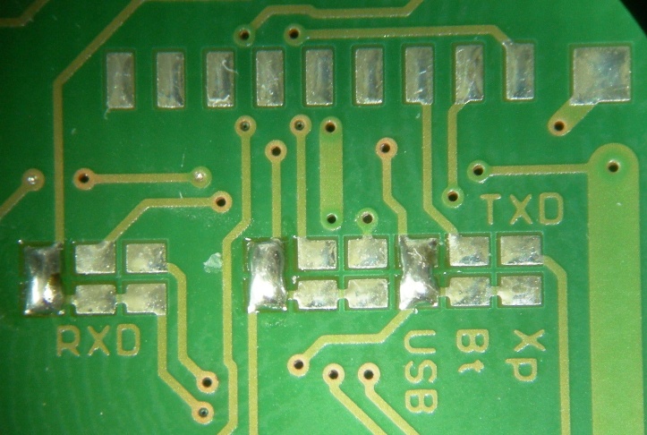
At minimum one solder jumper is always needed at the TX-Data multiplexer: In most cases it is the solder jumper named USB, which connects the serial output of the FPGA to the USB interface. The other possible selections are Xport and BlueTooth. Multiple connections are possible for TX-Data. RX-Data currently is not used.RTS-Handshake Signal is only used if you observe loss of data due to a large number of frames or due to a slow PC. It is explained later. It must only be connected to one of the output devices The default or fallback position of the DIP switches is all off, means towards the LED: 1MBit/sec over USB, no special funtion activated.In case of any problems with the Mode-S Beast, I always suggest falling back to this setting. |
The 10 DIP switches on the component side of the PCB |
DIP | Function (if set to ON) |
1,2 | Baudrate |
3 | AVR Format for transmission over Ethernet |
4 | DF11/17 filter: The Mode-S Beast only decodes DF-17 and DF-11 frames |
5 | MLAT timestamp enable |
6 | CRC check disable (for DF-11 and DF-17) |
7 | DF-0/4/5 filter: The Mode-S Beast does not decode those types (mostly used when having performance problems) |
8 | RTS handshake enable |
9 | 1 bit forward error correction disable |
10 | Mode-A/C decoding enable |
Baudrate | SW1 | SW2 | Usage |
3 MBit/sec (*1) | open | open | USB serial interface (with USB over FT232R only) |
921600 Bit/sec | on | open | Bluetooth interface (with Lantronix Xport or/and FT232R USB) (*2) |
230400 Bit/sec | open | on | Lantronix Xport interface (with BTM222 and Lantronix Xport) |
115200 Bit/sec | on | on | common standard for all interfaces |
Note that depending on your local traffic rate the interface baudrate is the real bottleneck of your system! So if you see a significant miss here, first introduce the DF-0/4/5 filter with DIP #7, and if that does not help, switch on DF17/DF11 filter with DIP#4.
The Mode-S frames capability of the different baudrates is about
Baudrate | rough number of frames per second maximum |
3 MBit | estimated more than 2000 |
921600 Bit/sec | 1100 |
230400 Bit/sec | 550 |
115200 Bit/sec | 300 |
These are very rougth estimations!!!
Mode-AC frames are transmitted with lower priority, so if your
interface is already conguested with Mode-S frames, you will see less
or no Mode-AC frames, too.
Planeplotter UDP Input Format | SW3 | Usage | ||||||||||||
disabled | open | Standard output:
with MLAT information:
The distinction between Mode-S and Mode-A/C is only done due to the length of the frame. |
||||||||||||
enabled | on | Only
necessary/used if 1. Lantronix Xport is used for network data transfer AND 2. UDP data transfer towards Planeplotter is used (there is also a COM port emulation for the Lantronix Xport, using TCP/IP between the Xport and the computer, which does not need the 'AV' prefix) Planeplotter then needs a prefix 'AV' in order to distinguish the data from other network data. Standard output: AV*02E99619FACDAE; AV*8D3C5EE69901BD9540078D37335F; AV*7700; with MLAT information: AV@016CE3671C7423FFE7AB7BFCAB; AV@016CE3671AA8A800199A8BB80030A8000628F400; AV@016CE3671C747700; |
DF-17 only | SW4 | Usage |
all standard data formats | open | The Mode-S
beast will decode all data formats that are currently used: DF-0, DF-4, DF-5, DF-11, DF-16, DF-17, DF-18, DF20 and DF-21 Note: DF-0, DF-4 and DF-5 can extra be filtered off with SW7 |
only DF-17 frames | on | Only DF-17 or DF-11 frames are decoded. Use this for example if you experience severe performance problems on the serial interface. |
MLAT enable | SW5 | Usage |
MLAT information off | open | No MLAT information is provided, data frames are initiated with '*' |
MLAT information on | on | MLAT
information is provided using a 12MHz (83ns resolution), all frames are
initiated with '@'. Note: On a later version I am planning a 100MHz resolution timer with 1PPS reset |
CRC disable | SW6 | Usage |
CRC on DF-11 and DF-17 | open | DF-17
frames are checked for a total match of the CRC DF-11 frames are checked for all but the lower 6 bits, which are the Interrogator ID and not usable for checking |
no CRC check | on | No CRC check is done for any frame. This can be used in conjunction with the CRC and biterror correction PC software driver or Planeplotter's FEC correction in order to get a higher frame rate. |
DF-0/DF-4/DF-5 filter | SW7 | Usage |
not active | open | if your setup is able to handle high load, this selection should be used |
filter all DF-0, DF-4 and DF-5 frames | on | These frame types are the ones with least useful information and so they should be the first ones that can be masked in case of interface or Planeplotter processsing overload. |
RTS Handshake enable | SW8 | Usage |
Hardware handshake disable | open | As long as you do not experience any data loss, hardware handshake is not necessary to be enabled. |
Hardware handshake enable | on | In
case of a high frame rate and/or togehter with a slow PC, it might be
useful to configure and enable RTS hardware handshake. It should be mentioned already here that this handshake is acutally not done between Planeplotter and the FPGA, much better it is done exactly between the interface device and the FPGA. More about that later. |
1 Bit FEC disable | SW9 | Usage |
Forward error correction enable | open | The CRC checksum of Mode-S frames allows a correction of up to 5 bits. 1 Bit errors are those appearing most often and are corrected with this feature by the Mode-S Beast. |
disabled | on | There is no bit error correction done in the Mode-S Beast. |
Mode-A/C frame decoding | SW10 | Usage |
disabled | open | No Mode-A/C frames are decoded by the Mode-S Beast |
enabled | on | Mode-S beast also decodes Mode-A/C frames Frame format see DIP#3 |
Solder jumpers are used to configure rarely changed functionalities as there are:
|
Solder jumpers are located on the bottom side of the PCB, RxData on the left, RTS in the center and TxData on the right The picture shows the full routing of signals for USB, as I normally do it before shipping. Note that RxD is optional and not NOTE (1): TX-Data can be routed to all output devices in parallel, so for HW Version 1.1 this jumper block will be removed anyway. But mind NOTE (2)! NOTE (2): If you intend to use Lantronix Xport, the outgoing RxD and TxD are swapped in HW-Version 1.0! That means that the outgoing TxD signal nees to be routed with a wire to the pad in the RxD multiplexer, like shown on this picture:Wiring of the Mode-S Beast for output using Serial-over-USB and Lantronix Xport at the same time. |