D: Seit langer Zeit kämpfe ich bei meiner EME-Anlage für einen deutlich besseren Empfang. Es scheint unumgänglich zu sein, die Verluste zwischen den einzelnen Antennen so gering wie irgendwie möglich zu sein. Nachdem das Verkürzen der Kabel zum Antennenkoppler bislang nicht den gewünschten Erfolg brachte, plante ich den Umbau auf Zweidrahtleitungen. Nach viel Überlegen und Diskutieren mit anderen OMs (tnx CT1DMK, DL9KR, G3SEK etc) ist mir eine Idee gekommen, wie ich die Antennen ohne Kreuzungen und Störstellen der Leitungen speisen kann. Dabei handelt es sich um ein komplett angepaßtes System ohne Impedanztransformationen.
Im ARRL-EME-Kontest 1998, Teil 2, habe ich hauptsächlich gerufen, und auf dem Bildschirm von FFTDSP immer wieder viele Anrufer gesehen, aber kaum oder garnicht identifizieren können. Im selben Wochenende brach mein bisher eingesetzter Antennenkoppler und der Umbau wurde nach langem Warten auf besseres Wetter im März 1999 durchgeführt.
VORSICHT! Werden die Speiseleitungen
zu den Antennen in Längenunterschieden von Lambda/2 ausgeführt,
so muß das entsprechende gespeiste Element ebenfalls um 180°
gedreht werden. Alle Antennen müssen phasenrichtig gespeist werden,
d.h. zur gleichen Zeit muß eine gleiche Phase auf derselben Dipolhälfte
sein. (danke, VE7BQH)
E: Since a long time I am fighting against weak receive performance at my EME antenna. It seems to be unavoidable that the losses between the antennas and the coupler must be made as low as possible. As just shortening the cables does not give sufficient success I am planning now to modify for parallel wire feed. After long thoughts and discussions with other hams (tnx to CT1DMK, DL9KR, G3SEK and others) I found the solution how to feed the yagis without mechanical problems. Its finally a system with complete match and without any transformations.
In the ARRL-EME-contest 1998 part-2 I mostly called CQ and saw many stations calling for me on the screen of FFTDSP but I copied them with great problems or even not a bit. During the same weekend my coupler broke due to cold temperatures, brass material and mechanical stress. In March 1999 I did together with the help of DC1MJK the modifications.
ATTENTION! If you make the feedlines with WL/2 different lengths then the element driven by that line must be turned 180deg compared to the others to maintain a correct phase. All antennas must be fed with same phase. That means that at one time there must be the same amlitude direction on the same half of the dipoles. (tnx VE7BQH)
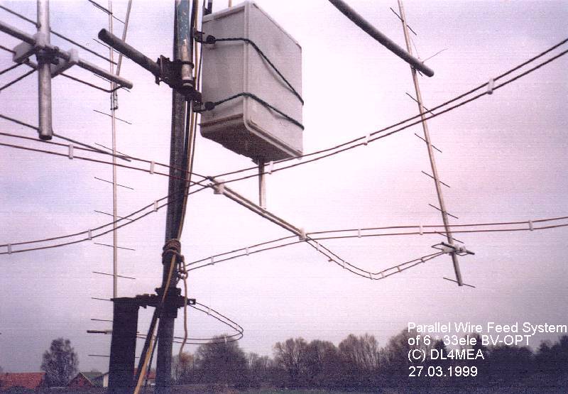
The T-shape coupler in the central of the array:
(click on the pictures to get them in high resolution)
 |
 |
 |
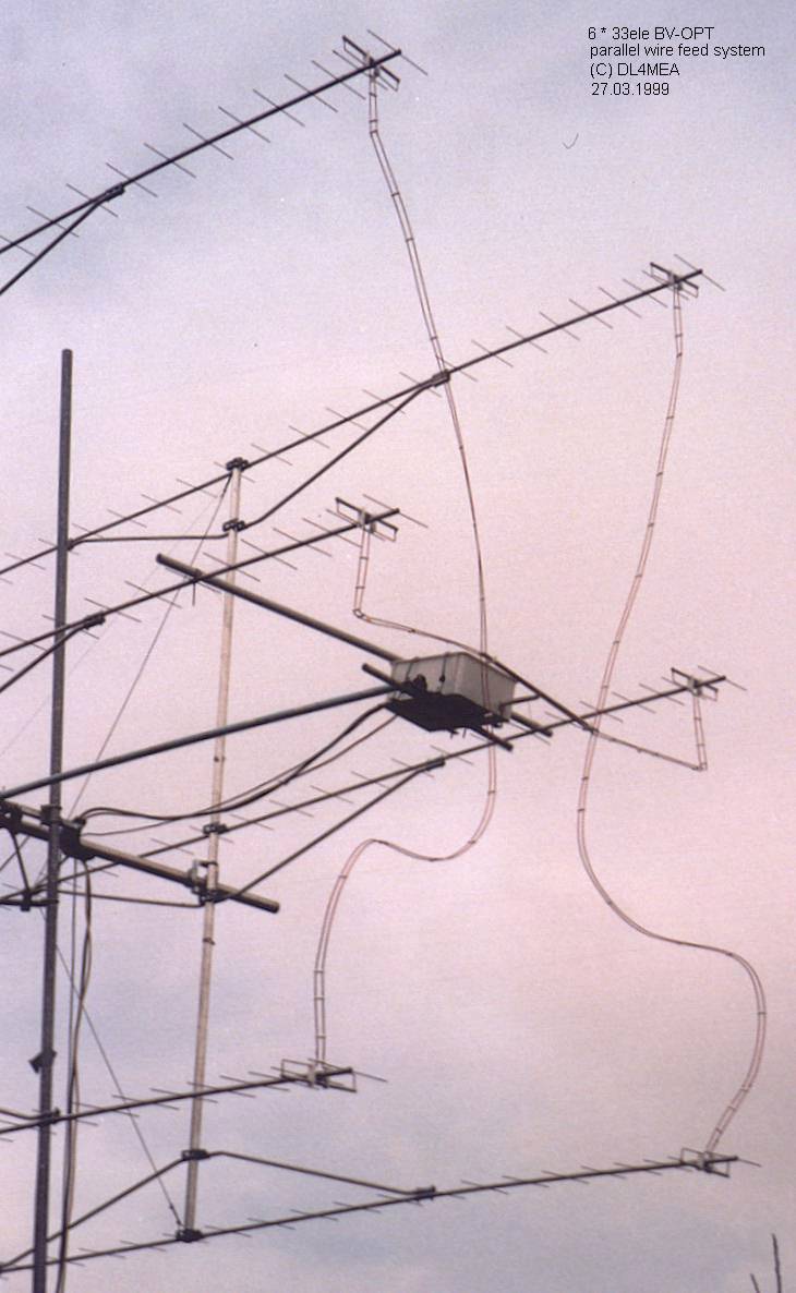
The feed lines:
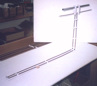
Middle antenna driven element with feedline. |
Mounting of the driven element:
|
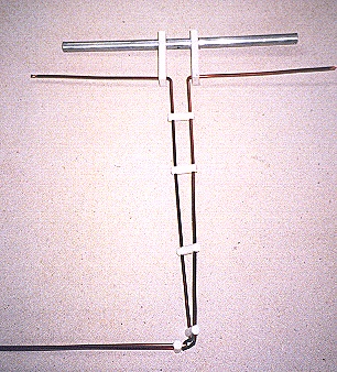
Driven element after mounting. |
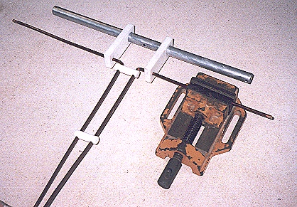
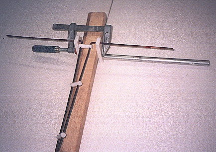
Bending of the wire using a simple drilling vice. |
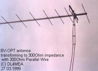
When I calculated the new transformation of the BV-OPT to 300ohm impedance
instead of the usually used 200ohm I found that this is possible using
4mm transformation lines. Nothing was closer to make the parallel wire
from the same material and therewith avoid one connection completly.
The feed lines are made from double varnished copper wires of 4mm diameter
with teflon spacers. Both wires have 24mm distance and give 300Ohm impedance.
Despite that they are already matched the length was hold to be multiples
of WL/2 as already done at the T coupler to give no transformation if any
misalignment happens.
It was a little hard to connect the wire at the end of the elements.
I put brass screws into the elements and soldered the wire there, but this
is not very nice. It would have been better for any rebuilders to replace
the 14mm element simply by a copper tube so you can simply solder both
together.
Driven element and parallel wire feed line installed at the antenna.
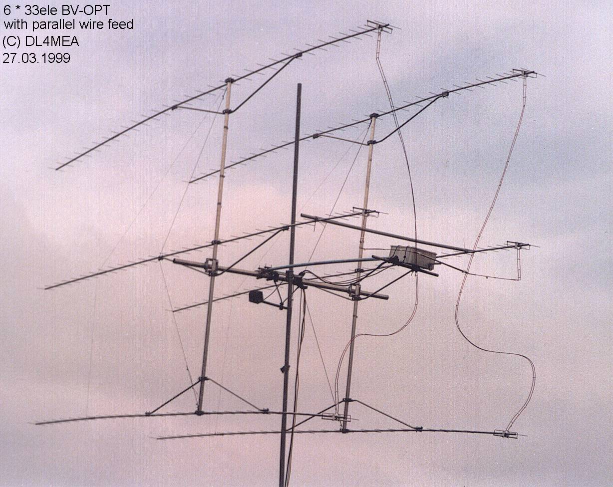
Complete Antenna:
 |
 |
 |
Miscellaneous:
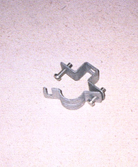
Mounting clamp for the feed elements to the boom. |
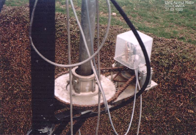
The azimut rotor of my EME antenna:
|