Lightweight 4 Element Yagi for 144.3MHz
Materials and description
The choice of the materials used should be a compromise between weight
and robustness. So this ended up at 1.4mm stainless steel rods and 11mm
PE installation tubing as used by electricians. For the beam to be
portable,
it is convenient to spit the boom into two pieces. The ideal solution
(in
my mind) is to used the ends for the middle of the boom, as they are
already
made to stick into eacs other. I drilled a whole through the joint boom
at the overlapping region. One now can kill two birds with one stone by
impaling the yagi at this specific drilling to hold the boom parts
together
and the antenna to the sky (see sketch). The elements sticked through
drillings
in the boom and fixed by hotglue. The driven element is tuned by
sliding
the rods in and out, until matched. Fixed then by luster terminals. The
driven element is built similarly to the 3-element-yagi presented in
the
ARRL handbook 2000.

Dimensions
| Element |
Material |
Dimensions |
Dist. to reflector |
| reflector |
1.4mm steel rod |
1035mm |
0mm |
| driven element |
1.4mm steel rod |
2x50mm |
416mm |
| 1st director |
1.4mm steel rod |
936mm |
831mm |
| 2nd director |
1.4mm steel rod |
926mm |
1290mm |
| boom 1 |
11mm PE tubing |
700mm |
-- |
| boom 2 |
11mm PE tubing |
700mm |
-- |
Simulation
The dimension of the driven element was measured after SWR-tuning. The
construction allows easy tuning as the element is fixed using a luster
terminal.
-------------------------------------------------------------------------------
YAGIMAX 3.0 CALCULATION OF 4 ELEMENT YAGI
ULTRA LIGHT YAGI AS BUILT
07-20-2000
13:37
FILE: DL1GSJ_R.INP
-------------------------------------------------------------------------------
ELEMENT: LENGTH (Cm.) SPACING
FROM REF. (Cm.) ELEMENT DIA. (Cm.)
Reflector:
103.5000
0
0.14000
Driven Ele.:
99.0000
41.6000
0.14000
Director #: 1
93.6000
83.1000
0.14000
Director #: 2
92.6000
129.0000
0.14000
-------------------------------------------------------------------------------
Normalized Radiation Resistance at 144.300 mHz is 55.71 Ohms
-------------------------------------------------------------------------------
FREQ (mHz) GAIN (dBi)
F/B (dB) IMPEDANCE
(ohms)
VSWR
144.000
9.09
12.04
49.69+j14.17
1.04
144.050
9.09
12.07
49.89+j14.43
1.03
144.100
9.09
12.09
50.09+j14.69
1.03
144.150
9.10
12.12
50.29+j14.94
1.02
144.200
9.10
12.15
50.48+j15.19
1.01
144.250
9.10
12.17
50.67+j15.44
1.01
144.300
9.10
12.20
50.86+j15.68
1.00
144.350
9.10
12.23
51.05+j15.92
1.01
144.400
9.10
12.25
51.24+j16.15
1.01
144.450
9.10
12.28
51.43+j16.38
1.02
144.500
9.10
12.31
51.61+j16.61
1.02
144.550
9.10
12.33
51.79+j16.83
1.03
144.600
9.10
12.36
51.97+j17.05
1.04
144.650
9.10
12.39
52.15+j17.26
1.04
144.700
9.10
12.42
52.32+j17.47
1.05
144.750
9.11
12.45
52.50+j17.68
1.05
144.800
9.11
12.48
52.67+j17.88
1.06
144.850
9.11
12.51
52.83+j18.08
1.06
144.900
9.11
12.54
53.00+j18.27
1.07
144.950
9.11
12.57
53.16+j18.46
1.07
145.000
9.11
12.60
53.32+j18.64
1.08
-------------------------------------------------------------------------------
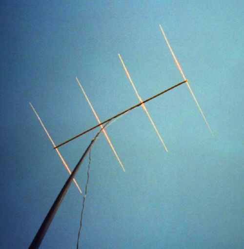
Photo
Yagi-Uda antenna held in the evening sky of Hamburg
Experience
Immediately after tuning the antenna went into the sky. Fortunately it
was weekend, so that a few station were operating 2m SSB. Good reports
and a good directional effect made me believe the antenna is worth to
be
presented. Without having planned to do so, I made several QSOs during
the scandinavian activity contest with 10W pep RF output.
Like the magnetic loop for 2m the beam is lifted in a hight of 3-4m
above the roof. For sure this does only work when there is no wind, as
the beam sticks to the telescopic mast where this is 4mm in diameter
only.