2m omni-directional antenna
(Squarooka - squared bazooka)


Concept

Sort of similar to the one of the 6m omni. Instead of using twin-lead, this design makes use of a more or less regular double bazooka antenna (coaxial dipole). Your attention shall be drawn to the available standart literature, such as Rothammel.
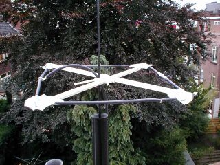
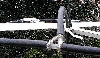
In order to "compute" the dimension, Karl Rothammel mentioned that the total length of the dipole shall be 95% of the free-space wavelength. The short-circuit bridges (closing the folded dipole) are to be placed at a distance-fraction being equal to the velocity factor of the coax cable used, which will be 66% using RG-58 or RG174.


Some Simulations....

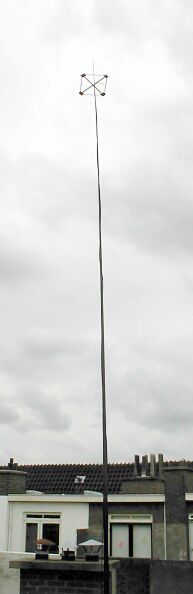
No sofisticated simulations have been done on this aerial... Just to give a short impression what can be expected, a very rough simulation using "real" ground setting with an antenna height of 9.5m (corresponds to a height gained by a DK9SQ "fibreglass telescope tower").


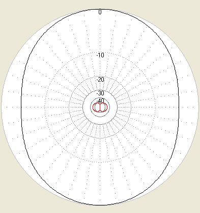
the horizontal directional diagramm


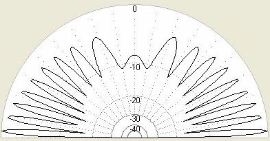
and for completeness, the vertical diagram too


Dimensions used for 144.350 MHz

Material used:
RG - 58 C/U
Total length RG58:
98.6 cm
Length of one dipole leg:
49.3 cm
Distance feed to short:
32.5 cm

Based on a free-space wavelength of:
( 299.79 / 144.35 ) m = 2.0768 m


Have a closer look

... and identify my favourite materials. The cross is made of some strange PVC profile this time. You might also recognise one short-circuit bridge on the front right of the square.


Construction

The difficult part in building a double bazooka antenna is cutting the coax. More precisely: NOT cutting throught vital parts of the coax cable, i.e. the braid.
As shown in the image below, the outer (black) insulation and the shield have to be cut, preferably w/o cutting into the dielectric...


This is the way I usually do these sort things:     
Next critical point: the short-circuit  bridges. A photograph of the finished product would be useless... and... I did not take any when tinkering things together....
Here is the way to proceed:
Go on with the remaining task building a cross, etc. BTW: You will need 35cm poles, building a square of 25 x 25 cm². Cable ties ... ... ...

I used duck tape to fix all together, including the joint of the dipole legs opposite the feed point (visible on the above photograph). Looks ugly, builds quickly.... good luck!


Experience

It was built just the day before this text came to see the cyber-world's light... therefore there was no time at all to do more than just an RX check-up. PI7CIS (JO22dc) tuned loudely in my Belcom LS-202E (which is not really surprising, since the beacon is just a couple of kilometers apart from my place in JO22eb). By turning the mast around a slight volume change could be heard, even though the S-meter reading did not really change.
Second rx-test (13.Sept.2003), with the FT817 this time, gave S8 on PI7CIS and S1 on GB3VHF (JO01dh)  and PI7PRO (JO22nc). Besides the beacons the band was quiet.... therefore still no tx-test.