
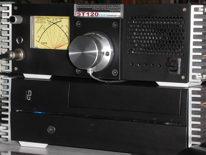
The complete equipment. Below the PC with heat sinks (because of the optics?) on the side and over the radio with SR-100, power supply, LF amplifier, loudspeaker, driver, PA and low-pass filter.
Some preliminary considerations
I'm a little disappointed with Flex Radio. Once upon a time. There were the four (formerly three) boards of the 1Watt version individually. As a kit, so to speak. Then there was the 1Watt version only together with a for my terms very expensive housing, which I did not want. Now there is only the completely assembled 100Watt version. Sorry for the experimenting radio amateur.
What do you do now, if you want to deal with the technology of the SDR, but do not want to buy a complete device. The only thing left is the meticulously accurate replica or the KDG-SR100 module from Kneisner and Döring / Braunschweig (Germany), which is disputed by some radio amateurs. Even if the measured values propagated by KuD are not as good as those of the SDR-1000 from FlexRadio.. But I'll talk to you later.
Since I had already experimented a lot with direct mixers and phase transmitters in the shortwave- sector in the 1970s, it is a logical consequence to link up at this point with considerably more modern means (building elements) and methods (software). In this case, a kit is the first choice when it comes to quickly becoming qrv at least in a receptive way and finding an entry point.
The result is a device that can certainly be described as - upper middle class. There is no need to shy away from the comparison with well-known devices such as KENWOOD TS450 or ICOM IC735, and of course the flexibility of the DSP is much better.
Firstly, the observation that the sensitivity values propagated are quite interesting, but in practice they are, in my opinion, not relevant. The single-board version of KuD shows worse measured values, but as long as the noise level increases when connecting a (large) antenna, I am on the safe side with the construction..
Any OM dealing with SDR-1000 or SR100 must be aware that certain circuit details need to be improved. Even Flex-Radio has created the RFE-Board in order to improve the filter parameters. Some radio amateurs are not satisfied with the large signal resistance achieved and they are experimenting with additional filters or tape passes. That's a good thing! With the SR100, the phase noise of the DDS circuit is added, because the TCXO does not work on 200MHz and therefore the internal oscillator with a PLL has to generate the high reference frequency.
Flex radio is also not infallible. Every designer who controls hardware via software provides a - watchdog - to protect the hardware from malfunctioning of the software. In the SDR-1000, the hardware is protected by the software-based monitoring of the standing-wave ratio! This is also quite questionable, especially since the end stage transistors used are not protected from too high SWR due to their internal design.
Top-class devices are not - single-board devices - !!! We only need to take a look at what our ancestors did in the 1930s to create top-of-the-range devices: RF-tight chamber construction and pre-selection with giant coil turret consisting of multi-circular belt filters with silver-plated coils to achieve high circular grades. I know from the occupation with the direct mixers still preselectors, which had to be tuned with frequency changes around 20kHz within the band! Since a preselector is - out - the means of choice in the upper class is therefore the simultaneous preselection via coordinated inductors, which has to be realized with great effort. And even with these devices, inductive tuning is controversial, because the nuclear material used may deteriorate large signal strength and intermodulation behaviour. Bandpass filters and low-pass filters, in addition with SMD components of low quality, are not sufficient for selection. Physics can't be outwitted.
SDR-1000, SR100 and also the future HPSDR are the basis for own experiments, no cooking recipes or even finished equipment of the upper class. Two considerations are important:
1. The dynamic range (signal-noise ratio)! S9 correspond to 54 dB, S9+40 dB correspond to 94 dB and when radio stations are added, one is fast at 110 to 120 dB dynamic range! Simple sound chips in PCs have a dynamic range of 70 to 90 dB. So you need a sound card for professional studio recording quality (e. g. Derta 44 by M-Audio). If this is not possible, one is dependent on preamplifiers and attenuators!
2. No nonlinear components (diodes) in the signal pathway because of the intermodulation behaviour! Run switch only with relays!
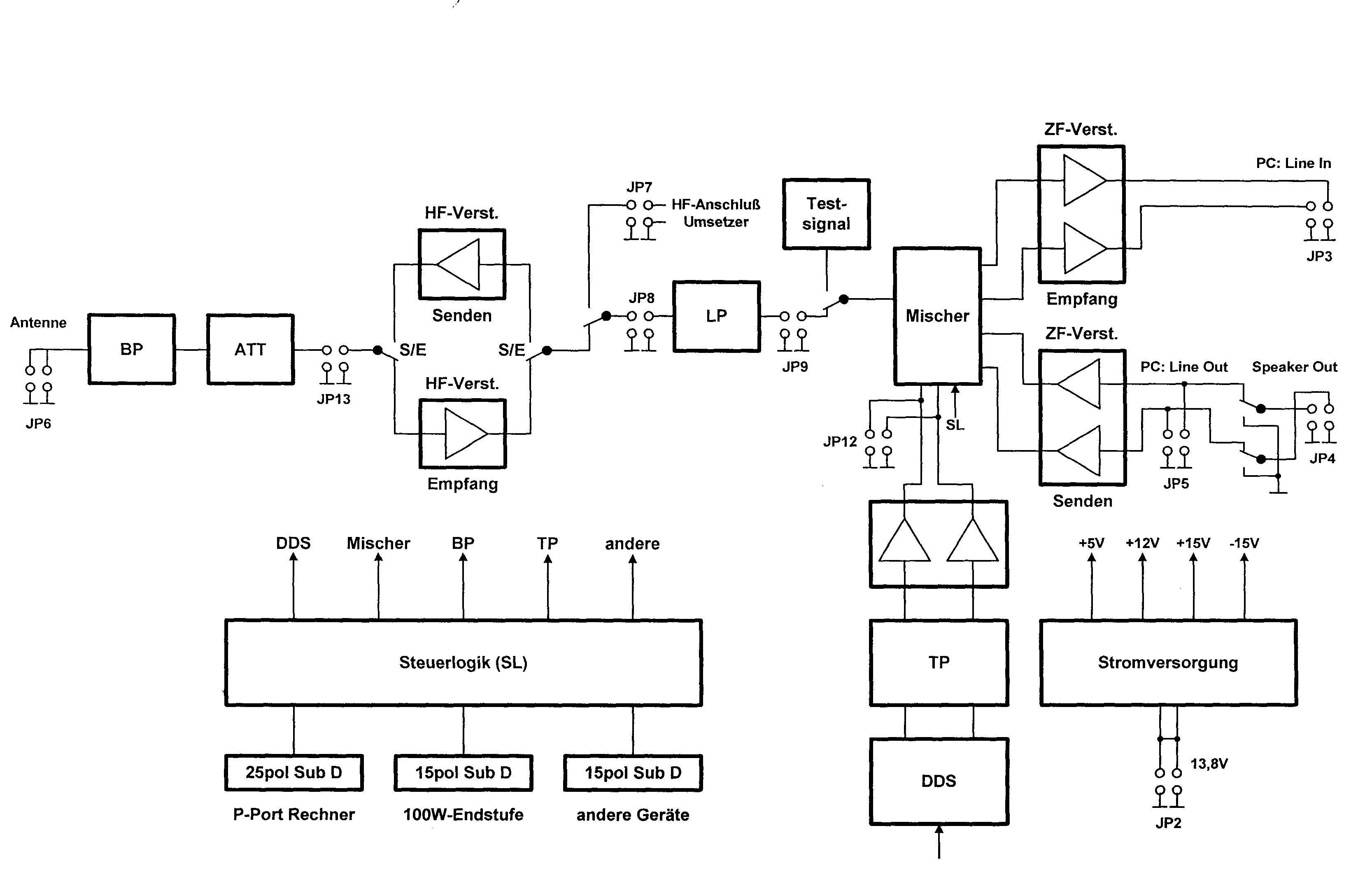
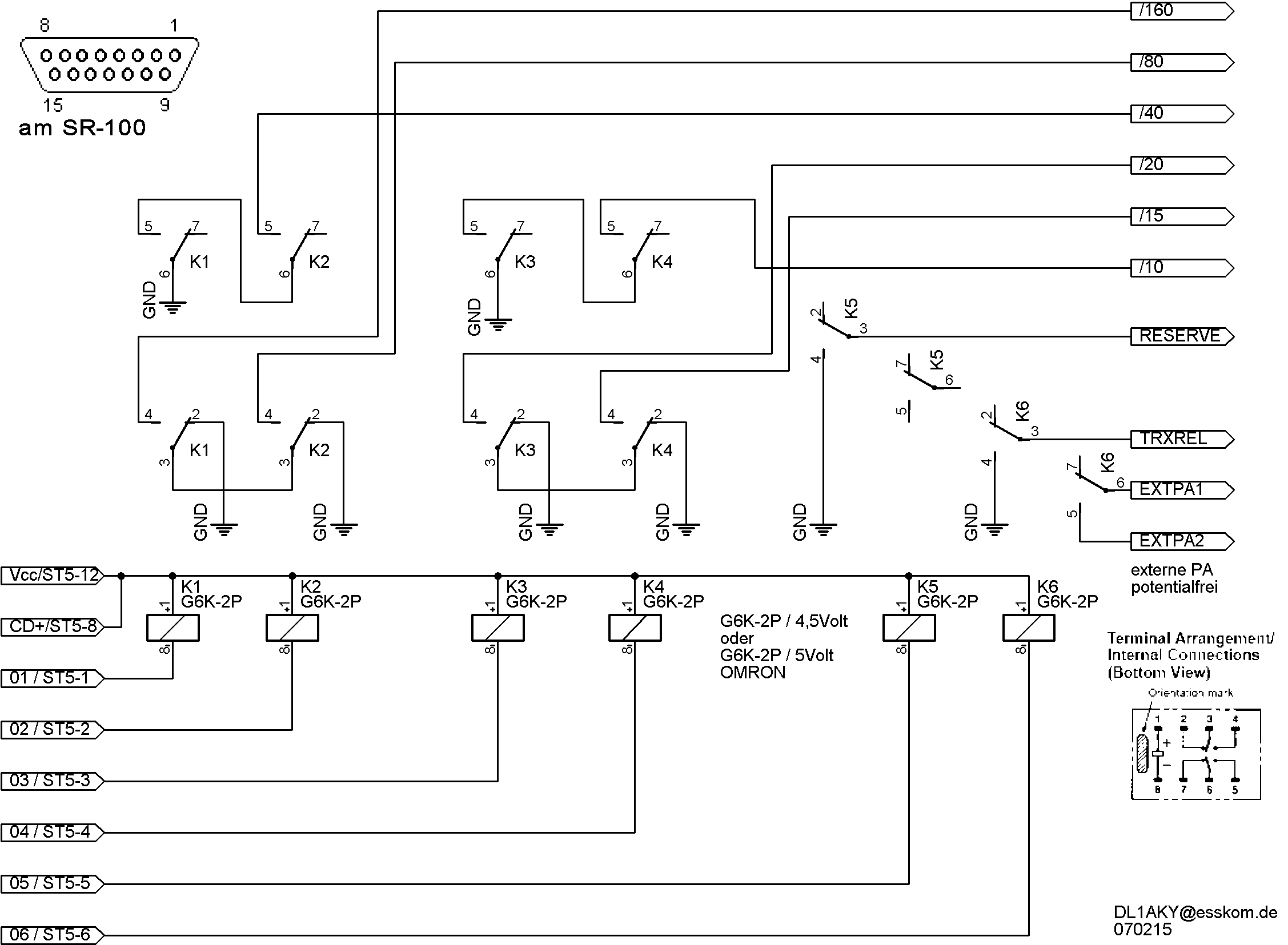
Block diagram
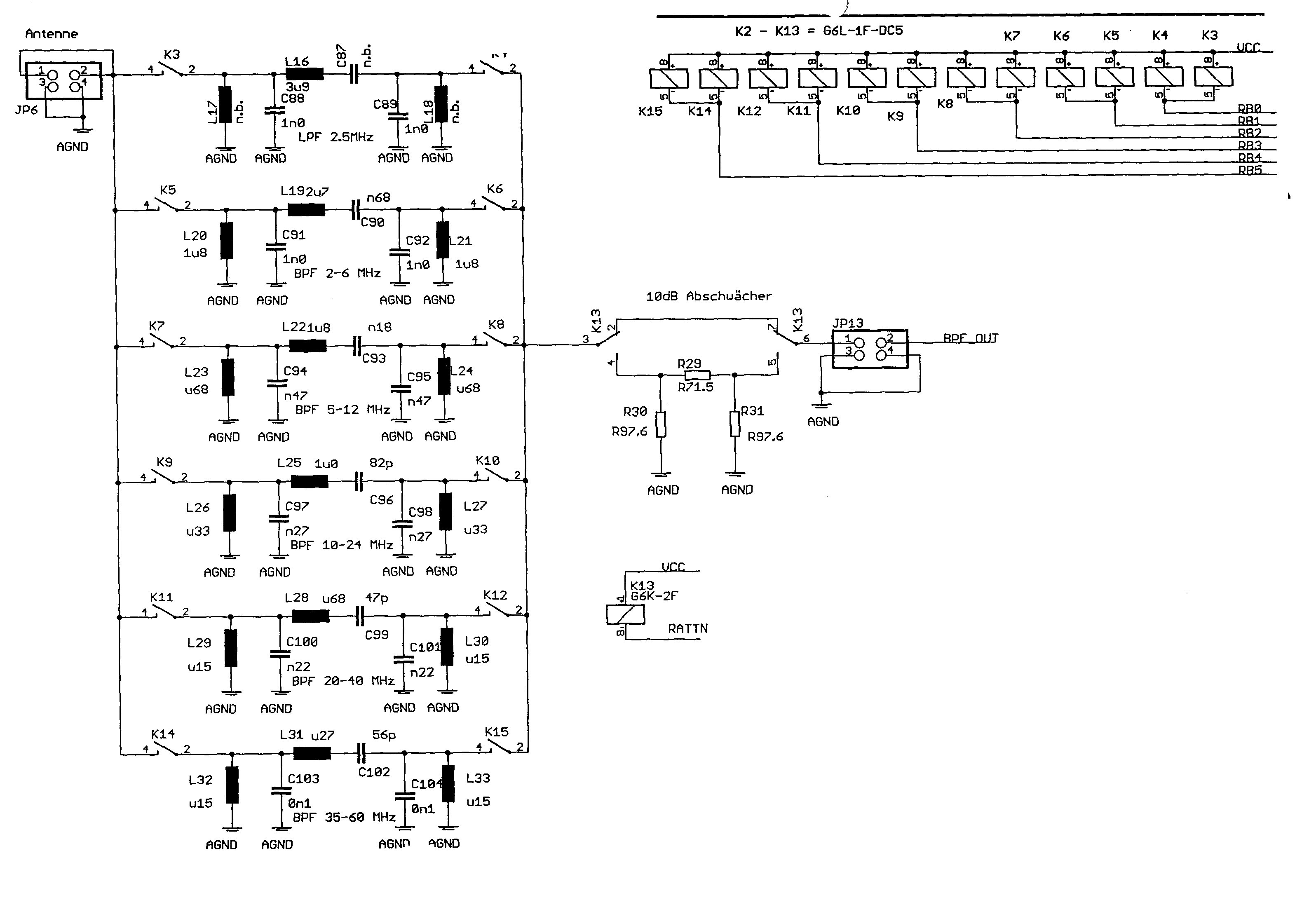
Bandpass filter
Here is the result:
View of the shell from the front. The potentiometers were intended for power control, but were then no longer used for further development. The loudspeaker and the LF amplifier are recognizable on the mounting front panel..
View of the shell from behind
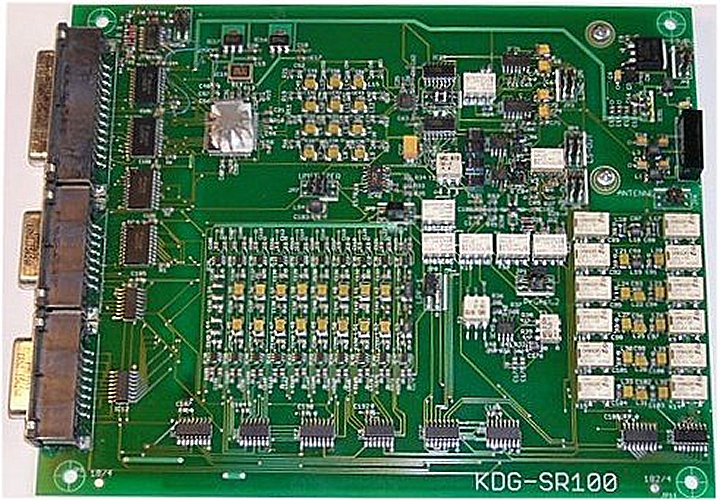
The SDR board
Easy to recognize: The large number of SMD relays especially in the area of the input filters.

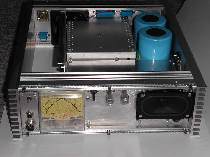
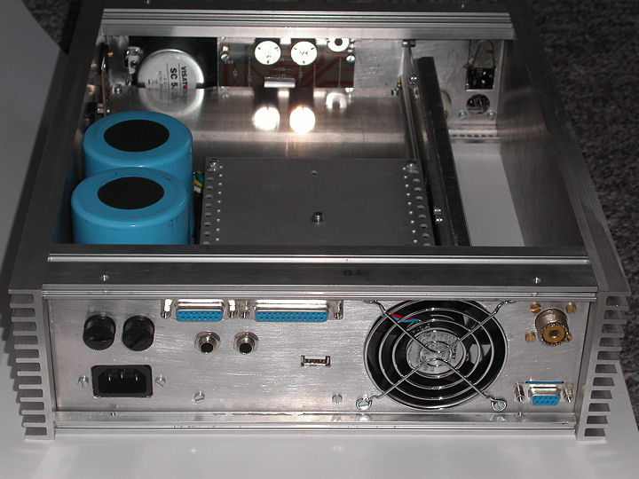
The SDR board in the housing. Underneath is the network transformer and the break-out box of the sound card. On the left the free space for the PA and on the right heatsink the longitudinal transistors of the power supply.

The PA module. On the left the drivers with the power control (monitoring / SWR protection circuit) and on the right the power amplifier with two bipolar transistors similar to MRF428 and MRF428 respectively. BLW95. In the exit 3 guanella transformers. Power amplification 27dB from 1. 8 to 30MHz. Maximum 250Watt HF at 500mW driver-control!

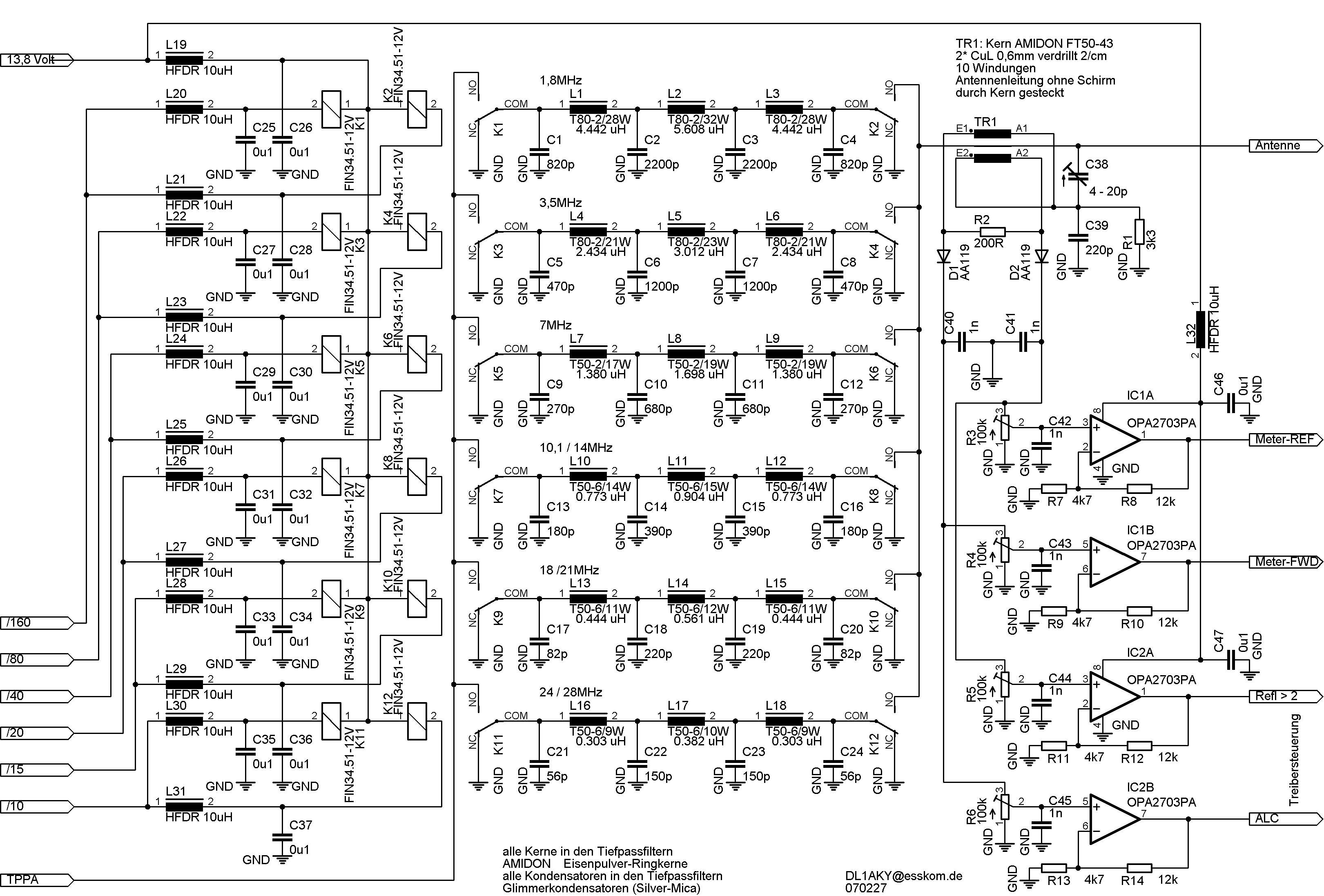
Lowpassfilter
Low pass filter It is used both in transmitting mode and in receiving case. The higher the frequency, the smaller the nuclei. The capacitors and RF chokes for blocking the control lines are arranged on the solder side. For interested parties here are the individual circuit details:
For interested parties here the individual circuit details:
(Please download pictures and display or print them with a graphic program on DIN A4)
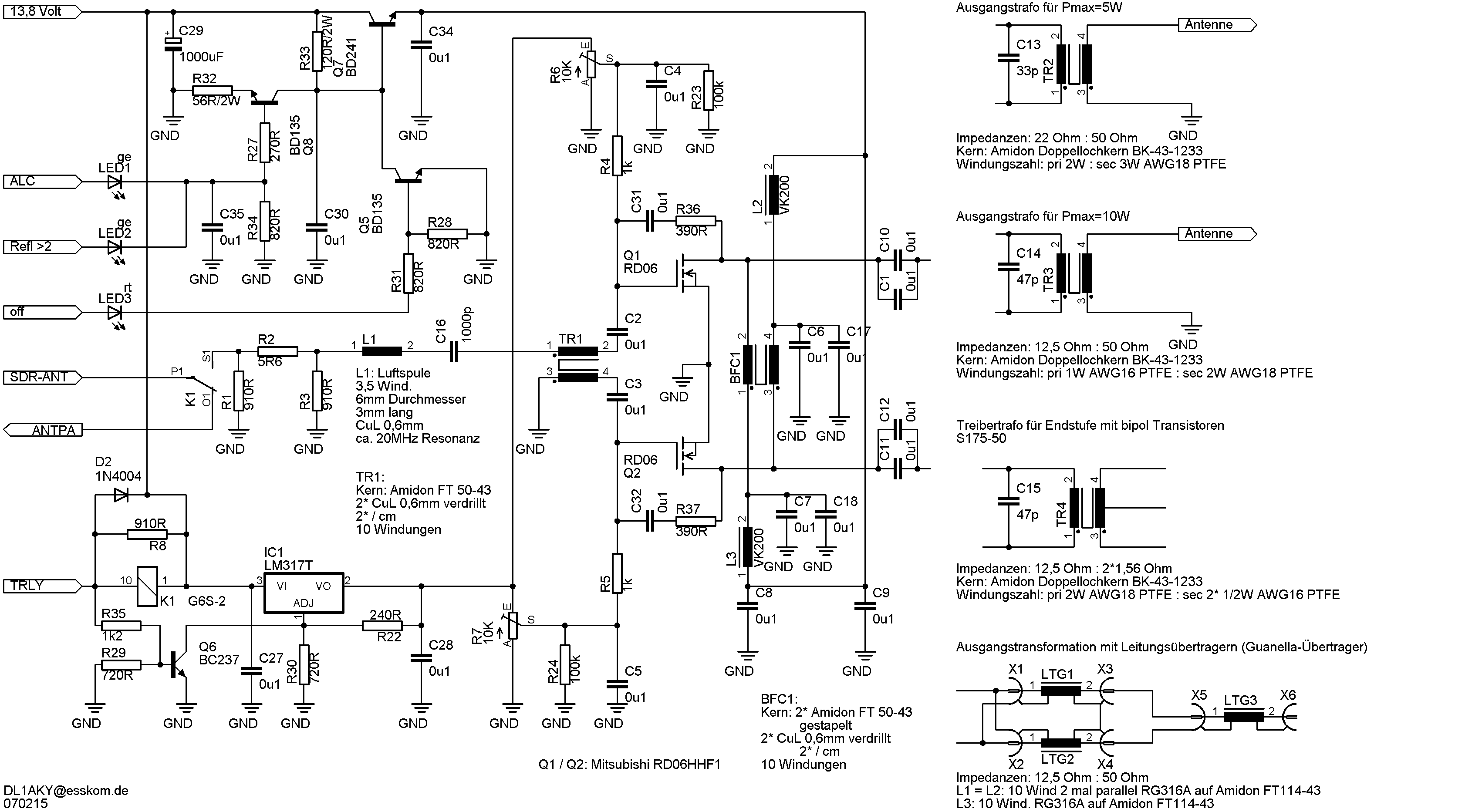
The driver with MOSFETs from MITSUBISHI. Different variants of the RF decoupling. Use of the ALC and control of the power with an SWR greater than 2 is not the normal operating case! These are states of error. Therefore, in my opinion, the power control via the operating voltage of the driver is justified. The deterioration of the intermodulation behaviour of the transistors only occurs in the event of an error. Transmitter power amplifier with bipolar transistors for 50 Volt operating voltage. Free according to MOTOROLA AN-758.
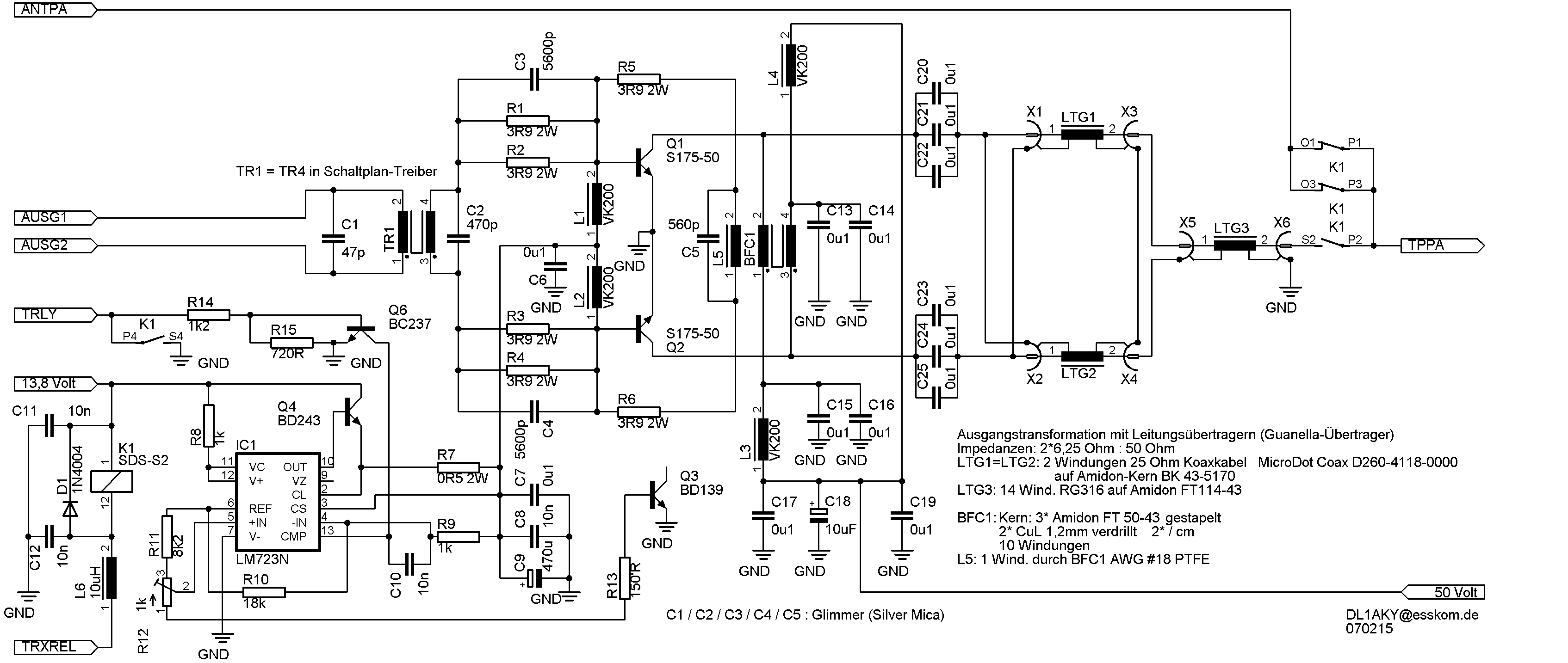
The transformation at the output takes place with line transformers according to GUANELLA. The 25 Ohm coaxial cable can also be connected in parallel to a 50Ohm cable (e. g. B. RG316). Low-pass filter and SWR measuring bridge. The surgical amplifiers are I/O rail-to-rail amplifiers, i. e. they come with one operating voltage! Here, of course, the quadruple type OPA4703 can also be used. Control circuit for connection to Ext. Ctrl. of the SDR. So you have two additional control lines and at the same time a separation between the SDR and the peripheral assemblies is realized. The corresponding settings for - Ext. Ctrl. in the PowerSDR setup.
Low-pass filter and SWR measurement ceiling. The surgical advisors are I/O rail-to-rail operators, i. e. they come with an operating voltage! Of course, the four-fold type OPA4703 can also be used here.
Control circuit for connection to Ext. Ctrl. of the SDR. So you have two additional control lines and at the same time a separation between the SDR and the peripheral assemblies is realized.

The associated settings for this - Ext. Ctrl. in the PowerSDR setup.
We reserve the right to make changes to the product(s) or information contained herein without notice.
Thanks to PONS for the help with the translation !