Theory for the Zig-Zag Antennas Practical Construction


An unconventional Antenna Family -

the VHF/UHF Zigzag Dipoles

Although sharp focusing antennas have a high antenna gain in the main beam direction, the downside of this property is, however, that one does not hear or is not heard outside the sometimes very narrow main lobe. For this reason, in certain cases antennas with large horizontal opening angles are extremely useful.

Particularly in the case of contests, antennas have proven themselves in a stooped design, which have a large horizontal at a small vertical opening angle. For example, in the case of AGCW VHF / UHF short-term tests, such antennas are a tried and tested alternative to directional antennas. But also in the normal portable operations you can appreciate the advantages of large opening angles. For this I have used stacked oblong radiators [1] so far. For a long time, I have been working on solutions for horizontally polarized VHF antennas with large horizontal and small vertical opening angles. As the experiments show, the antennas described here can be mechanically even easier to achieve comparable antenna gains. This opens up a wide field of activity for experiments.


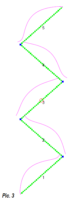
Theory of the Antennas

For this, let us look first of all  how normal stacked Dipoles for horizontal polarization change their impedances (Figure 1). Taking the normal length of a dipole for 145 MHz (impedance 72 +/- j X 0 Ohm as basis, then the impedances shown there are modified. The reason for the other data is easy to see. The immediate proximity of further resonant dipoles results in considerable feedback on the radiation resistors, in the real and imaginary part. The two inner dipoles each have two neighbours, the outers only one and the free space. This explains the greatly different impedances. The necessary length corrections for a real radiation resistance without blind parts is the easier exercise. In addition, the stacking cables for the four feed points with different impedances need to be executed to be added to a connection point of 50 Ohm.  Because of this, I have been looking for simpler solutions to get along with only one feed point.

One possibility is the use of stacked oblong loops, as described in [1] and [2]. However, it should also be possible to find a simplified arrangement for stacked dipoles.

If you search for "zig-zag" or "Zick-Zack" antennas in the Internet, you will find a different definition from that described here. This refers to antenna shapes which allow a spatial shortening for the construction in the short-wave range for half-wave emitters or long-wires through this particular arrangement. This shows a certain relatedness to fractal antennas and has nothing to do with the stacked arrangement of half-wave dipoles presented here.

I found the basic idea of ​​the stepped dipole line in zig-zag arrangement on a Ukrainian website [3]. It was probably more common in the Russian aerea as a "snake antenna" with 5 sections earlier. With EZNEC [4] I have calculated different versions with and without reflectors and also built up practically. In addition, two different types were tested for feeding. For this purpose the sections are simply stacked at 45 ° to the axis. The original description refers to a version with vertical polarization, 5 dipoles and central feeding. At the opening angles, however, horizontally polarized arrangements are significantly more useful.


Usually, in the case of a collinear stacking of dipole lines, quarter-wave stubs are necessary for phase-correct interconnections of the individual sections. With the antennas described here it greatly simplifies the design. The ends of the individual dipoles can be connected to one another. The correct phase position is set automatically by the  90 ° angle.

For the understanding of the principle you can use the double quad in "diamond" form, which is also horizontally polarized, although the radiating sections are arranged at a 45 ° angle to the polarization plane. This is almost a version with half-wave elements of this well-known antenna form, which however has only 3.5 dBd as gain. But the 4-element zig-zag constructed with the same material requirement (four half-wave sections) has significantly higher gain at 4.7 dBd. This is due to the larger vertical stacking distance of the radiating elements.

Although the main extent is in the vertical plane, the zig-zag antenna (abbreviated ZZ) radiates with horizontal polarization. For this reason, the antenna is not affected by a vertical metallic holding mast. A prerequisite is, however, that a certain minimum distance is adhered to. For portable operations it is enough if the antenna is placed on the front of a fishing rod and the coax cable on its back. When mounting on a metal mast, a distance of 10 cm should be maintained. Correspondingly, vertical polarization is achieved when the antenna is rotated by 90 ° and it is mounted transversely to the support.

As the number of elements increases, the vertical opening angle becomes smaller and smaller. The horizontal opening angles of the double-sided radiators with an even-numbered dipole arrangement are approximately 84 ° for all variants with the feeding in the middle and are greater than for all other comparable antennas.

Central feeding of odd-numbered ZZ antennas

An example is the 5-element ZZ antenna. A provisionally structured model with 2-mm aluminum wire (Figure 2) initially gave, without further adjustments  of  the calculated lengths a SWR from 1.3 on 144.5 MHz.

This because the feed resistance is 235 Ohm instead of the optimal value of 200 Ohm for the half-wave transformation (see below). Figure 3 shows the arrangement of the elements with the feed point at the center and the element currents which occur. In Image 4 (horizontal directivity pattern) is to be seen that in relation to normal dipoles lowering transversely to the axis is not shut up to 0. Even with an attenuation of 15 dB, reception can still be possible from this direction, which is not an undesirable effect. The antenna gain of 6.15 dBd concluded exclusively by bundling the beam width of the vertical pattern as seen in Fig. 5


Asymmetrical feeding in the lowest section

Normally, the feed point is placed in the middle section. If a certain asymmetry of the directional diagram is accepted, one can also feed the lowest dipole. The advantage is that the whole antenna can be attached to a fishing rod or a similar support and the coax cable is only moved a short distance behind the antenna. In addition, the supply cable becomes shorter. Here the analysis shows that the variants with this asymmetric feed and even-numbered sections show almost symmetrical diagrams in both planes. In the case of those with odd-numbered ones, the diagrams are significantly more deformed.

If the coax cable is connected in this way in the first section, the result is a highly interesting regularity: as the number of elements increases, the gain growth decreases relatively. However, a further, highly desirable enlargement of the azimuth angle crystallizes out. This increases to 95 ° for 8 elements, or 103 ° for 10 elements. At the same time, the lowering is reduced transversely with respect to the axis, whereby the diagram approximates more closely to a circular radiator. However, the asymmetrical ZZ antennas should not go beyond 8 elements because the lobes are raised too high in the vertical diagram.

One remains in the design, that all portions have equal lengths, as is particularly evident when looking at the element currents in Figure 6 wherein the 8-member-ZZ an interesting phenomenon. The lower sections are too short for a whole half wave and should actually be lengthened. The further you get up, the smaller the effect is to end the current distribution of the wave trains agrees to 4 again. However, due to the occurring phase jumps, the attenuation decreases transversely to the antenna level and drops to 8 dB. With an antenna gain of 7.4 dBd, this still corresponds almost to the gain of a normal dipole at 90 ° to the axis!

For comparison with the mid-powered antennas it is worth taking a look at the free space diagrams. Figure 7 shows the larger opening angle of 95 ° in the azimuth plane can be clearly seen. Figure 8 shows that the vertical beam width is very slightly raised with 1 ° upwards. This is still acceptable for this antenna, but with an increasing number of elements this effect is counterproductive with further reduction of the opening angle.


The feed resistors increase with the number of the stackes dipoles, the overall characteristics  I have summarized in Table 1 below. It is interesting for the simulation that, if the basic structure is correct, it is generally sufficient to make minor changes in the length at the upper end in order to reach impedances without a blind part. It is relatively easy to calculate the possible or planned total antenna height itself. Depending on the type, an overall height of approx. 80 cm is to be planned for each segment. Thus for 10 sections one reaches about 8 m total length.

Table 1: Data of zig-zag antennas for the 2-m band in the summary


Height

Feeding

Gain

Impedance

3-dB-Angle hor.

3-dB-Angle ver.

4-element

3.08 m

down

4.78 dBd

  200 Ohm

85 °

37.5 °

5-element

3.87 m

center

6.15 dBd

  235 Ohm

84.3 °

27.0 °

6-element

4.72 m

down

6.53 dBd

  276 Ohm

88.8 °

23.1 °

7-member

5.50 m

center

7.52 dBd

  330 Ohm

83.4 °

19.4 °

8-element

6.32 m

down

7.47 dBd

  340 Ohm

95.4 °

16.9 °

9-element

7.20 m

center

8.56 dBd

  444 Ohm

83.4 °

14.6 °

10-element

7.90 m

down

8.32 dBd

  460 Ohm

103 °

13.3 °


Summary of the results

  1. The arrangement at 45 ° angles to the axis results in a simple, phase-correct stacking of horizontally polarized dipoles.

  1. From three sections onwards almost as many dipoles can be stacked vertically with increasing gain. You need only one feeding point at a time.

  1. When an odd-numbered arrangement (3, 5, 7, ...) is fed in the center, the horizontal opening angle is approximately 84 ° with bidirectional radiation. The vertical opening angle decreases with the number of elements.

  1. There is a difference between even and odd sections. The asymmetry in the vertical plane is significantly greater for odd-numbered dipoles than for an even-numbered arrangement. As a result of the occurring phase shifts at the connected points, the horizontal opening angles become ever greater and reach values ​​above 100 °. In addition, the descents transversely to the axis become increasingly smaller and approach a circular radiator with the ellipsoidal shape. As the dipole number increases, a slight shift of the vertical radiation angle occurs.

  1. In all variants, the feed impedance increases with the number of elements.

  1. The individual dipoles are significantly longer than lambda / 2 and its length increases with the number of the stacked sections.

  1. In contrast to normal dipoles, the elements have to be lengthened in the case of zigzag radiators with larger diameters. This is analogous to full-wave loops, which are also subject to this effect.

  1. If blind components are present, they can be compensated within certain limits by lengthening or shortening the end elements. In the case of the unsymmetrically-fed forms, it is sufficient to correct only the uppermost section.

  1.  If the lowest element is fed slightly out of the midth in the case of the asymmetrical variants, impedances without blind components can be realized, which allow easy matching.


Variants with reflectors

It is possible to make a true directional antenna from the bidirectional. For this purpose,  reflectors with aluminium tubes must be arranged at the points with the highest element currents, similar to the double squares and quadlongs, which also makes it possible to raise the gain above 3 dB. However, the lengths change significantly, and the feeding impedance decreases considerably.

The trials are not yet finalized and should be described at a later date. For the SHF bands, antennas are conceivable in front of a reflector wall, which are easy to set up and feed.


Sources:

[1] Steyer, M. (DK7ZB): Eine Vierfach-Oblong-Antenne, CQDL (82) 2011, Heft 5, S.  

[2] Steyer, M. (DK7ZB): Horizontale Rundstrahler für UKW, FUNKAMATEUR (65) 2015, H. 2, S. 182-185

[3] http://www.antentop.org

[4]: Programm EZNEC+ Ver. 6.0.12 von Roy Lewallen (W7EL), P.O.Box 6658, Beaverton, OR 97007, USA  (e-Mail [email protected]), http://www.eznec.com

[5] Steyer, M. (DK7ZB): Neues von der 28-/50- -Anpassung und weiteren Varianten, FUNKAMATEUR (66) 2016, H. 2, S. 158-159