 |
Test Super Antennas Portable-Yagi YP3 by DK7ZB The Yagi from Super Antennas was tested the first time by IS0/DK7ZB in September/October 2009 on Sardinia Island For all details about the antenna read the manual:
|
| 2-El.-6-17m-V. Mk Vl |
Test YP-3 |
|
Test Super Antennas Portable-Yagi YP3 by DK7ZB The Yagi from Super Antennas was tested the first time by IS0/DK7ZB in September/October 2009 on Sardinia Island For all details about the antenna read the manual:
|
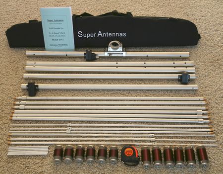
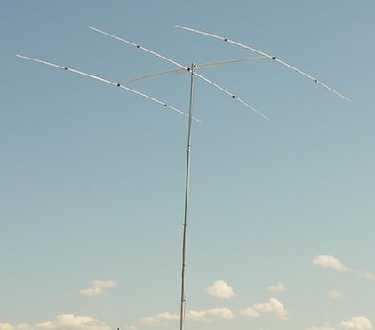
| The YP-3 is a 3-Element-Yagi with a lightweight
construction and a clever system for changing the lengths and the
resonant frequency of the beam.
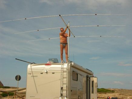
As a short conclusion I can say: An excellent antenna for the portable operator! I made some simple modifications for better performance on 6 m and 12 m and a greater mechanical stability of the boom. An additional coax-choke for surpressing common waves is easy to build. The results for DX with 100 W RF and a 9 m high mounting above ground were indeed surprising! |
|
 |
 |
 |
|
 |
 |
|
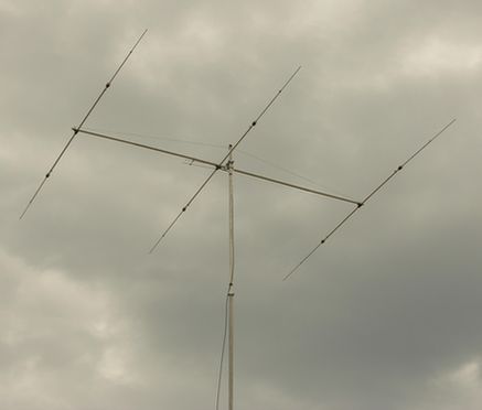
Without any support in stormy weather |
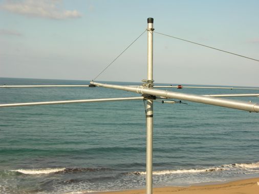
Additional support with a 2,5-mm-steel rope |
 |
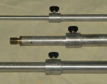
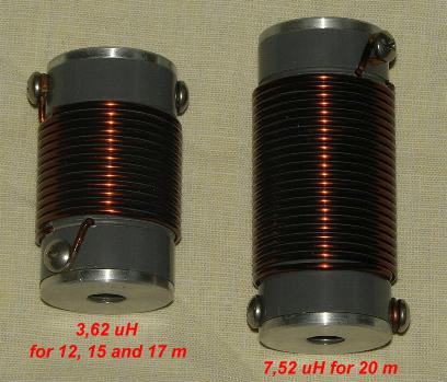
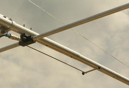
The YP-3 has a hairpin-match (Beta-match) with a
variable middle part for impedance matching.
30 m above salt water gives additional 6 dB groundgain and S9-signals on 17 m from JA in the sunspot minimum! The measured SWRs below are for a height of my mast 9 m above ground. Changing to another band is done in 10-12 minutes. |
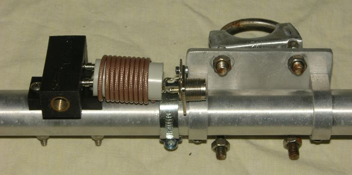
| The choke for a balanced feeding.
10 turns of RG188 PTFE-coax on a PVC-tube 25 mm. Without the choke my IC-706MK-IIG (it is very sensitive to RF injection!) I had interferences on SSB in the head- phones while transmitting. |
 |
| 50 MHz: Only SWR-test possible, no band conditions.
|
| With this modification you get an 28-Ohm-Yagi. The gain increases from 5 dB to 6,8 dBd. Remove the hairpin-match and use a DK7ZB-choke (2xlambda/4 75 Ohm coax). Bandwidth with SWR <1,5 50-50,5 MHz |
|
| 28 MHz: Only SWR-test possible, no band conditions.
|
| 24 MHz: Very good results, signals 1-2 S-units better than with a
quarter-wave vertical.
|
 |
Elevation pattern 10 m above ground, 0 dB = 11 dBd
|
| With a small modification I changed the
YP-3 to a 3-El.-Fullsize-Beam with 6 dBd gain and very good pattern.
Remove the loading coils, the hairpin-match and the original end-pieces.
Use the DK7ZB-match for 12,5 Ohm impedance.
Take the inner parts: 5/8 x 30 '', ½ x 28 '', 3/8 x 22'' New end parts: 6x1-mm-rods (see table right) |
|
| 21 MHz: Good results, the beam works like a
normal trap-beam, SWR for positions CW
|
| 18 MHz: Very good results, comparable to a
good 3-El.-Trap-Beam
|
| 14 MHz: Better than expected, F/B 1-2
S-units. First SWR for position CW, the second for SSB
|