Last update: 13-September-2001
|
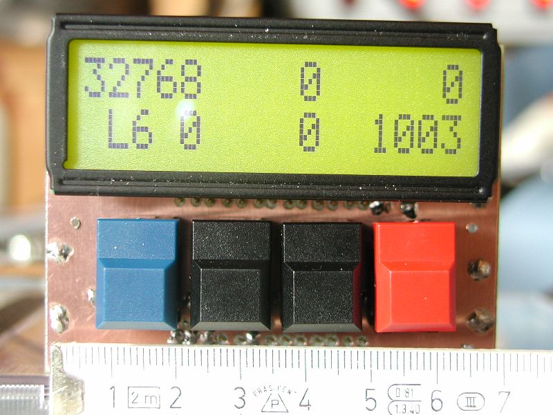
CRO-LCD A small PCB for a 2-line LCD and 4 buttons. It can be directly connected to the CRO board. |
- Download a .zip file (385KB) which consists the schematics etc. as pdf and the EAGLE V4.01 layout files.
|
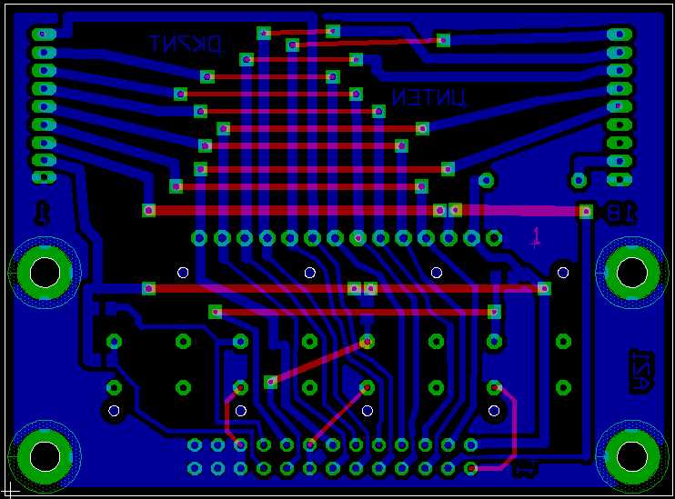
- Both layers in one picture, top view.
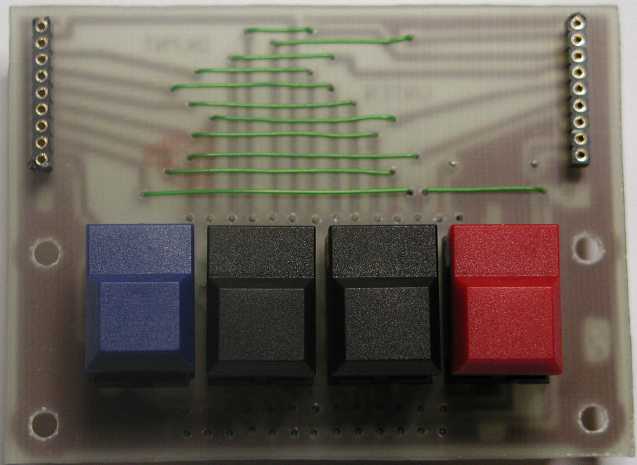
- PCB top view
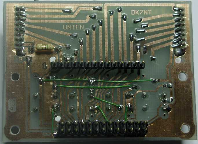
- PCB bottom view.