
2. Receive Functions
2.0 Introduction
JUDSP3 is operated by 3 knobs and 14 push buttons on the front panel.
The handling is similar for all functions. After switching power on you can select a function by pressing the MODE-keys. With these keys you can scroll through the functions in both directions.
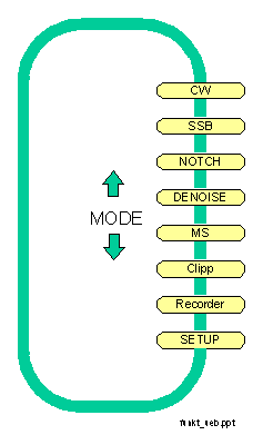
Usually the display shows in the
- first line: MODE and the selected settings (bandwidth ...)
- second line: the transceiverstatus (RX/TX) und the bargraph for the input level
With SET you can select settings (bandwidth ...) and with the "direction keys" they can be changed. Two kinds of display are possible:
1. the selected parameter ist marked with ^^^ in the second line
or
2. the selected parameter is shown in the second line.
The selected parameter can be changed by pressing the "direction" keys. The input level bargraph is disabled during that time. With SET you return to the normal display (that is the display with the bargraph).
By pressing REC just after changing the parameter the new value is permanently saved.
Pressing the buttons D and N activates in some modes the automatic Denoise and automatic Notch filter.
2.1 CW-filter for HF and VHF/UHF
Mode CW is a narrowband filter (5 - 800 Hz) with variable center frequency (400 - 1000 Hz). A special feature ist the distinction between filters for HF and VHF/UHF:
HF-filter are optimized for supression of unwanted signals. They have a high shape factor and high ultimate rejection.
VHF-filter are opimized for improving the readability of weak signals and reduced "ringing".
With SET you can switch from normal operation to changing the parameters filtertype, bandwidth and centerfrequency.

In normal operation (display bargraph) you can activate a spotting tone exactly on the center frequency by pressing STOP. The volume can be adjusted in 6dB steps with < and >.
Notch and Denoise can be activated at any time by pressing the N and D keys. Usually notch does not make sense, because it will suppress the CW-signal you want to hear.
The filters uses the TRX jack (see appendix A1.5.1) do differentiate between receive- and transmit-mode and shows the mode at the beginning of the second LCD-line as "RX" or "TX". On transmit the filter is bypassed so that any sidetone, monitorsignal etc. can pass without filtering.
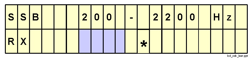
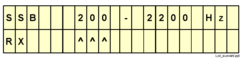
2.2 SSB-Filter
Mode SSB is a broadband filter for voice.
With SET you can switch from normal operation to the menus for changing the lower and upper cutoff frequency of the bandpass. Press the REC-key to permanently save the new settings.

Notch and Denoise can be activated at any time by pressing the N and D keys.
The filters uses the TRX jack (see appendix A1.5.1) do differentiate between receive- and transmit-mode and shows the mode at the beginning of the second LCD-line as "RX" or "TX". On transmit the filter is bypassed so that any sidetone, monitorsignal etc. can pass without filtering.
2.3 Automatic Notchfilter
The automatic notchfilter has a bandwidth of 50-3500 Hz. Within this bandwith multiple heterodynes, CW and computer "birdies" can be suppressed at the same time.
The notch-function can be controlled by two parameters (N and d). Select the corresponding menus with the SET-keys and change the value of N or d with the "direction"-keys.With the REC-key the values are permanently stored. Be carefully when changing these parameters, because some settings will make the notchfilter inoperative.

Parameter N is the order of the filter. With higher order you get better suppression of heterodynes but the time, to adapt to new or keyed heterodynes (CW) increases. So CW is better removed with a small filterorder.
Parameter d is the length of an internal delay line. The delay ist important to distinguish between the wanted and the unwanted signals and is adjusted to minimal distortions of the wanted signal.
The filters uses the TRX jack (see appendix A1.5.1) do differentiate between receive- and transmit-mode and shows the mode at the beginning of the second LCD-line as "RX" or "TX". On transmit the filter is bypassed so that any sidetone, monitorsignal etc. can pass without filtering.
2.4 Automatic noise suppression (denoise, peak)
The automatic noise suppression (sometimes called "denoise" or "peak") has a bandwidth of 50 - 3500 Hz. The filter adapts automatically to the wanted signal so that any noise beside the signal is suppressed.
The denoise function can be controlled by two parameters (v and d). Select the corresponding menus with the SET and change the value of v or d with the "direction"-keys. With the REC-key the values are permanently stored. Be carefully when changing these parameters, because some settings will make the denoise filter inoperative.
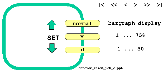
Parameter v ist the amplification factor of the internal control loop. It determines how fast the filter follows changes in the signal. Parameter d is the length of an internal delay line. The delay ist important to distinguish between the wanted and the unwanted signals and is adjusted to minimal distortions of the wanted signal.
The filters uses the TRX jack (see appendix A1.5.1) do differentiate between receive- and transmit-mode and shows the mode at the beginning of the second LCD-line as "RX" or "TX". On transmit the filter is bypassed so that any sidetone, monitorsignal etc. can pass without restrictions.
2.5 MS-recorder
The digital MS-recorder can record HSCW (High Speed CW) signals up to 10,000 lpm and replay with a reduced speed of down to 1/90.
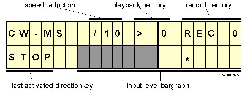
The record time is approx. 75 sec [150 sec with 2 MByte memory]. The memory is devided into 14 separate memory areas. The length of each memory area is variable and depends on the record time. The memorys are numbered from 1 to 14.
The memory area, which is used for playack, ist called playbackmemory. Playbackmemory 0 indicates, that nothing is recorded until now.
The memory area, which is used for next recording, is called recordmemory. Recordmemory 0 indicates, that nothing is recorded until now.
The last direction-key activated is displayed at the beginning of the second line of the display.
To prevent loss of data due to a long reactiontime when starting recording, an indiviual reactiontime may be configured, thus preventing any lost data during reactiontime.
Change of speed-reduction and reactiontime is done with the SET- and "direction"-keys.

2.5.1 Record / playback
This is the normal mode of operation. The LCD-display show the input level bargraph. Control of the individual functions is done with the "direction"-keys (like a tape-recorder).
|
|< |
The next playback starts at the begin of the actual playbackmemory. It the actual positions is already at the begin, than position changes to the begin of the preceding memory. |
|
<< |
Fast playback backwards. The speed is about 3 times that of normal playback. This helps e.g. to find the exact beginning of a burst. |
|
< |
Playback backwards. |
|
STOP |
Playback resp. recording is stopped. The AF from the transceiver is fed to the loudspeaker. |
|
> |
Playback. Playback starts at the position, where it was interrupted or positioned with |<, <<, >> or >|. See chap. 2.5.2 how to change the speed. |
|
>> |
Fast playback: the speed is about 3 times that of normal playback. This helps to find a specific point within on record. |
|
>| |
The playback-position changes to begin of next playbackmemory. |
|
REC |
Begin recording. The next recordmemory is selected and the input signal is recorded until any key is pressed. |
Example for recording High Speed MS:
2.5.2 Speedreduction
With SET select the speedreduction ( ^^^ marker on the LCD under 1/10). With the direction-keys you can select the speedreduction between 1/10 and 1/90. Press REC if you want to keep this value permanently.
By reducing the speed the pitch of the signal becomes too low: a 1000 Hz signal becomes an 11 Hz signal when reducing the speed to 1/90. JUDSP3 uses an automatic pitchcontrol, which gives a pitch of 800 - 900 Hz regardless of speedreduction.
2.5.3 Reactiontime
From hearing a burst until pressing REC there is a short reactiontime. This results in loss of the first characters of the burst. To avoid this, JUDSP3 is able to compensate for the reactiontime. This time can be individually specified from 0 to 1 second in 0.1 second steps.
Example: Your reactiontime is 0.4 sec, the configured reactiontime is 0.5 sec. Then there is 0.1 sec noise at the beginning of every recording.
Attention: The compensation of the reactiontime is also active when stopping the record. If your reactiontime at stopping is better than at starting, than the last characters might get lost.
Configuring the reactiontime: Select the display "Delay = x.x sec" with the SET-keys. With the direction-keys you can select a value between 0 and 1 second. For permanent storage of reactiontime press REC.
2.5.4 Bandwidth of High-Speed CW
To utilize the very high speeds offered by JUDSP3 you must pay attention to some details, because CW signals (on/off keying and AF injection keying) with this high speed have a significant bandwidth which must be available on the whole communication path, (trnasmit and receive side).
The MS-recorder uses a bandwidth of 35 - 3000 Hz. The bandwidth of most transceiver is about 150 - 2400 Hz. The pitch of the received CW-signal should be adjustetd to the center of this bandwidth: that is about 1100 Hz. Filtering with the "right" bandwidth is done by the MS-recorder with optimal CW filters. Even expensive crystal and mechanical filters have a varying groupdelay near the cutoff frequencies, which distort the signal. So the cutoff frequencies of these filters should be far away from the wanted signal.