D J 8 W X
JO43SV
Longwave site
My first transmitter
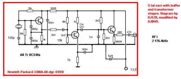
The generators
RF I
RF II
FT1000MP,
2 312.1 - 2 314.2kHz
Precision

The mixer
The filters are modified 455kHz IF band filters.
The Driver
R1: trimmer to adjust the drain voltage of IRFP451 to half of the operating voltage of the PA.
Driver output and PA input are matched by step-down transformation in toroid To 16 /4 windings.
The PA
T2: twelve N-CHANNEL IRF730. T3: eighteen P-CHANNEL BUZ173. T2 and T3 are mounted
on alublocks, each type of one`s own block and each of one`s own fan. matching the output
Z3,5 Ohm to Z50 Ohm I use toroid of Al 3000, Ur = 1 / 24 windings. R6: trimmer to adjust the
total rest current of PA MOSFETS to 500mA. C5: five 1uF/1000V.
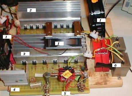
1=Cooling fans for alu blocks and output coil. 2=N-channel block. 3=P-channel block. 4=Driver.
5=output coil. 6=output condensers.
The autor
of the diagram is DL9AH/Arno (CQ DL 10/2001, page 731). The diagram is modified
by DJ8WX/Uwe.
The PSU
T4: five IRFP451 mounted on alu block. C2 abt 100uF/250V and R11 abt 60kOhm
make it that the operating voltage is running slowly to its peak of 200V (needs
abt 8 sec). The rectifiers (single diodes) are mounted on aluplates. Z1 must be
of high quality - if not you will blow up the PA MOSFETs because of the needle -spikes- generated in the PSU. Not shown: a capacitor 0,2uF and a discharge
resistor 3kOhm parallel to C3.

1= PSU for the cooling fans. 2= C3. 3= C2. 4.= Alu block with T4. 5= diodes of Br1 on cooling plates.
6= C1.
back
to