D J 8 W X
JO43SV
Longwave sites
Aerial loading coils / variometers
Five
years back from now (2002) my first aerial was a simple endfed longwire. The
facts:
136kHz-endfed-wire-aerial: Calculation of the inductance of the loading
coil.
λ = 300 : 0,136 = 2205,89m
H = l :
λ x 360˚ = 245
: 2205,89 x 360 = 39,99˚
S = l :
d = 245 : 0,003 = 81667
Z = 60
x ln(1,15 x 81667) = 687Ω
X C = Z :
tanH = 687 : tan39,99˚ = 687 : 0,84 = 818Ω
Compensation
of XC by inductive reactance XL
XL
= XC = 818Ω
L = XL
: (6,28 x f) = 818 : 0,854 = 958μH
λ wave length (metre)
H
length of aerial wire in angular degrees
l
length of aerial wire (metre)
S ratio
of length to diameter (Schlankheitsgrad)
d
diameter of aerial wire (metre)
Z
impedance of aerial (Ohm)
XC
capacitive reactance (Ohm)
XL
inductive reactance (Ohm)
L
inductance of loading coil (μH)
Since about four years (2000) I have tried out different kinds of transforming
the energy of transmitter outputs to three different aerials (L-aerial length
340m, LL-aerial length 70m and a vertical 16m high with elevated 0,8mH coil and
three top wires 70m each). Aerial stream and a wave form as sinusodial as
possible were the indicators for the efficiency of the transformers. The
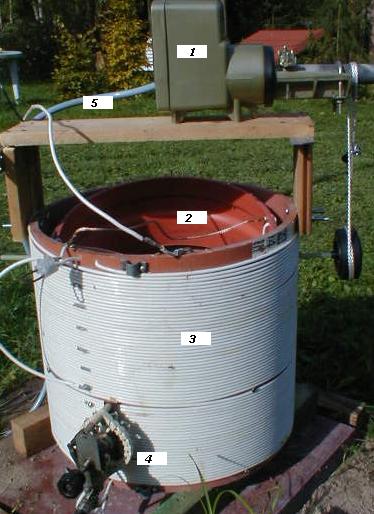
results are (remotely tuned) variometer circuits with which the fixed and the
variable coils are connected in series - described below. Both coils lie on one
and the same axis. The other kind of variometer, with which the inner coil is axially rotated
(see foto), did not stand the test.
The following
fundamental statements are extracted from
"Evaluation Regularities" of the RegTP, "Antennenbuch",
"Radio Handbook", "Amateurfunk Lexikon" , "Dezibel
& Co.", "Radio Engineers Handbook" and the most is
from e-mails of the LF reflector (tks to the OMs). Measurements and
calculations refer to my station.
I.The variometer for the 340m long inverted L aerial.
The output impedance of TX is (via
50Ω coax
RG213U abt 80m long) matched to the impedance of the aerial system by finding a
suitable point at one of the first windings of the fixed coil opposite the
connection to the variable coil (switch "4"). This
kind of matching has to be changed. It has to be a (remotely) tuneable
variometer too instead of a "tapping" mechanism.

L1 =
208mm (length of the fixed coil), L2 = 110mm (length of the variable coil), D1 =
404mm (diameter of the fixed coil from centre to centre of wire), D2 = 364mm
(like D1 for the variable coil), n1 = 30 w (number of windings. At 8 windings I
did find Z=50Ω for 150W HF power
and at 7 Windings for 800W). n2 = 16 w, c = 6mm (space between centres of
neighboring windings), d = 3,5mm (diameter of wire without insulation. the
"wire" is a 70 wire litze of tinned copper) s = 2.5mm (space between
neighboring windings without the insulation).
Inductance of separate outer coil = 0.370mH, of separate inner coil =
0.121mH, inner and outer coil connected max.= 0.813mH.
1.The Q-factor
The
"Q" of the above described coil en toto is:
Q = XL / R = (2πfL) / R
= 854.513 x 0.813 / 2 = 347,4
(XL
= reactance in Ohm , R = loss resistance in Ohm - 2Ω - and f = frequency in kHz, L in Henry).
According to the program "solnoid2" by G4FGQ the static coil has a Q
= 397 and the variable has a Q = 264.
2.Bandwidth
b = fres/Q = 136000 / 347,4 = 391,5Hz
The
result of measurement: b = (Ufres+ x 0,707) - (Ufres-
x 0,707)
- under
construction -
II.The variometer for the 70m long inverted LL-aerial
L1 =
320mm, L2 = 180mm, D1 = 319mm, D2 = 269mm, n1 = 72 w, n2 = 26 w, c1 = 4.5mm, d1
= 2.5mm, s1 = 2mm, c2 = 7mm, d2 = 3.5mm, s2 = 2.5mm. Inductance of outer coil
=1.122mH, inner coil = 0.160mH, inner es outer coil connected max. = 1,889mH.
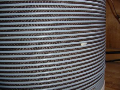
Part of the high Q loading coil for the LL aerial.
The
space "s" of the LL-loading-coil (see image) is filled with a cord
fixing the windings. The ratio wire diameter (3,5mm) to pitch (distance from
centre to centre of adjacent windings, 8mm) is 0,44 (0,5 would be best, see the
program "solnoid2" by G4FGQ). "d", "c" es
"s" are important if "Q" of coils must be high. A good
ratio minimizes distributed capacity which can cause losses up to 20% of the
overall losses because electrostatic energy storage involves dielectrics (isolation,
coil former and other things near the coil), see Radio Engineer`s Handbbook
p.84.
1.The "Q" of the variometer coil en toto is:
Q = XL / R = (2πfL) / R =
854.51 x 1.889 / 4 = 403,5
2.Bandwidth
b = fres/Q = 136000/403,5 = 337Hz
The
result of measurment: b = (Ufres+ x 0,707)
- (Ufres- x 0,707)
- under construction -.
III.Radiation resistance of the 16-m-vertical
Remark:
Radiation resistance - ok it is a fictitious value (P.784 Radio Engineers
Handbook).
1. Calculation without taking the elevated coil into consideration:
Cv = (24h) / log([1.15h] / d). CVertical part in
pF, h = 16m and d = 0,0035m.
Cv = 384 / 3,72 = 103pF
Ch = (24 l) / log([4h] / d). CHorizontal part in
pF; l = 3 x 70m.
Ch = 5040 / 4,26 = 1183pF
Rrad = 0,082([ 2Ch + Cv] / [Ch + Cv])2 x h2 = 77,5mΩ.
2. Calculation taking the elevated coil into
consideration but not the horizontal parts:
Rrad = 0,082 x (hL + h)2. hL = height of the elevated
coil (11,6m).
= 0,082 x (11,6 + 16)2 = 62,5 mΩ.
Rrad of
a vertical monopol aerial with elevated coil (height 16m, coil height 11,6m)
according to progr "Loading coil" by G4FGQ = 50mΩ.
3. Other Calculation without elevated coil and without horizontal parts
of the antenna:
Rrad = 1579(heff
/ λ)2 =
1579(12,38 / 2200)2 = 50mΩ. 1579 = (377 x 4π) / 3.
Vice versa:
h-eff
= λ x √(Rrad
/ 1579) = 2200 x √(0,05/1579) = 12,38m.
IV New load coil for the 16-m-vertical with elevated coil

L from ground terminal to Z-50-Ohm match = 45uH (must be 58,5uH for Z-50-Ohm at 136kHz).
L from Z-50-Ohm
match to aerial terminal = 313uH (with 75uH of the rotary coil)

This is the phasemeter
of Volt and Ampere at the PA output indicating whether the tuning of the
matching coil is correct (Z = 50 Ω) or not. It was a CB –Radio SWR meter: Remove
the PCB and install the coils, capacitances and diodes leading to the
indicators. At left and right side are connectors for a dual trace
oscilloscope.
back to