D J
8 W X
J O 4 3 S V
Radioamteur site
The Self-Evaluation and plausibility check
for
German Radio Amateurs
Field
Evaluation
Evaluations
based on
Calculations
(0,136MHz to 29,7MHz) and
Measurements
(136kHz)
I. Information
by RegTP on Radio Amateur Self-Evaluation
Under the Amateur
Radio Act (AFuG) in conjunction with the Amateur Radio Ordinance (AFuV)
and the
Telecommunications Type Approval Ordinance (TKZulV) amateur station operators
must
demonstrate to the RegTP
their compliance with the personal safety and cardiac pacemaker
limits.
Order 306/1997 of the
now defunct BMPT lays down the plausibility check procedure, with the
limits designed to
protect persons exposed to RF fields and the basic procedure for radio
amateurs to
demonstrate their compliance with the limits.
Given the aim of
independent and responsible participation set forth in the AFuG, the RegTP
has not laid down any
detailed calculation or measurement methods for radio amateurs to
demonstrate compliance.
Numerous papers,
comments and programs related to the self-evaluation and plausibility check
procedure have been
published. However, not all of them shed enough light on the procedure. The
following information
has therefore been published to aid radio amateurs in evaluating the
compliance of their
fixed amateur radio stations:
Evaluation of the Site
Surroundings
Evaluation of the
Fixed Amateur Station
Choice of Field
Evaluation
Evaluations based on
Calculations
Numerical Evaluations
Evaluations based on
Measurements
Estimation of
Compliance
The aim of the RegTP's
plausibility checks is not to certify compliance with the limits under
Order 306/1997. The
RegTP certifies compliance under the site certification procedure only.
Field Evaluation
The following
definitions and principles apply to the choice of field evaluation for the
self-evaluation and plausibility check procedure.
Reactive near field:
between the antenna and
A near field evaluation is made where the calculated compliance distance
is in the reactive near field.
Radiating near field:
between
In the case of most types of antenna the compliance distance calculated
in a far field evaluation is longer than that calculated in a near field
evaluation where it is in the radiating near field. The amateur station
operator can therefore check if a simple far field evaluation can be made, depending
on the site layout.
Far field:
from 4l
A far field evaluation can be made where the calculated compliance
distance is in the far field
Evaluations based on
Calculation
Permissible deductions
(transmitter power) for personal protection limits Two deductions are
permissible in calculating the compliance distances for the personal
protection limits: - Deduction to allow
for the duty factor (FB) The personal
protection limits are met where the effective field strengths (rms average
over 6‑minute periods) are not exceeded.
Example: Maximum
transmission duration: 3 minutes
FB = 0.5 If the maximum
transmission duration is > 6 minutes, the deduction to be
made is FB = 1. - Deduction to allow
for the type of modulation (FM) Any deduction made to
allow for a specific type of modulation must be substantiated. If no specific
deduction is made, a standard deduction of FM = 1 will apply. - Calculation of the
total permissible deduction (F) The total deduction F
which can be made in calculating the compliance distances for the personal
protection limits is the product of the two deductions FB and FM
(F = FB * FM). The deduction F can be
converted into dB (F [dB]) for the following calculations using
equation [1]: F [dB] =
10*log(F) [1] No deductions
(transmitter power) for cardiac pacemaker limits Angular discrimination If antennas with a
horizontal or vertical radiation pattern are used, a deduction can be made in
evaluations based on calculations to allow for the angular discrimination.
Deductions made must be substantiated by the relevant radiation diagrams. No
deduction can be made in evaluations based on measurements because the
measurement results take account of the angular discrimination. Calculation of the
compliance distances (far field evaluation) Procedure for the
calculation of the compliance distances for the personal protection and
cardiac pacemaker limits: Personal protection
limits The mean power (PM)
is required to calculate the compliance distances for the personal protection
limits. Cardiac pacemaker
limits The maximum
instantaneous power (P) is required to calculate the compliance distances for the
cardiac pacemaker limits. If only the peak envelope power (PEP) or mean power
(PM) is known, the maximum instantaneous power (P) can be
calculated using the conversion factors for different classes of emission in
Table 2 of DIN VDE 0848 Part 1 (Oct 1995). The power can be
converted from W into dBW using equations [2a] and [2b]: Personal
protection:
PM [dBW]= 10*log(PM [W]) [2a] Cardiac pacemakers: P [dBW]= 10*log(P[W]) [2b] The antenna gain
required for the plausibility check data sheet is the antenna gain relative
to an isotropic radiator (gi [dB]). The gain relative to a
half-wave dipole gd [dB] can be converted into the isotropic gain
gi [dB] using equation [3]: gi [dB] =
gd [dB] + 2.15 dB [3] The antenna
discrimination in dB can be deducted from the antenna gain where appropriate. Personal protection Calculation of the
transmitter power (PM') for calculation of the compliance
distances (equation [4]): PM' [dBW] =
PM [dBW] - D [dB] + F [dB] [4] where D [dB] = loss between
the transmitter output and antenna input, Applicable personal
protection limits Electric and magnetic field strength limits
(EgP, HgP) as given in Order 306/1997. Applicable cardiac
pacemaker limits Cardiac pacemaker
limits in Draft DIN VDE 0848 Part 2 (Oct 1991) as given
in Order 306/1997. The compliance
distances (without account of the site surroundings) may be calculated using
only the electric field strength limits (EgP and EgHSM). |
Evaluations based on
Measurements
If the amateur station operator cannot
calculate the compliance distances because of the operating conditions or
site layout, compliance with the limits in Order 306/1997 must be
demonstrated through measurements. A major factor in the plausibility of
measurements is the choice of test points. Choice of the test points must
enable compliance with the limits applicable on the boundaries of the
property and in areas intended for the non-transient presence of persons to
be demonstrated. In cases of doubt the test points must be agreed with the
RegTP as provided for by Order 306/1997. II. The results with fixed station DJ8WX |
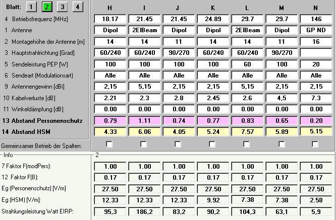
Evaluations based on
Calculations
EMVU-Plausibility
check using the EXCEL makros of the program Watt32 by DF3XZ.

Evaluations based on Measurements on consultation with the officials of
RegTP conc. 136kHz
E- und H-
fieldstrength measurements on 136kHz using the equipment PWRM 1 + HFS1 +
EFS1 absolut calibrated by order of DJ8WX. The Measuring points (MP) are found
in the aerial-view foto on the site "aerial arrangement". Excel-makros
by DL7FO.
|
|
|
|
|
|
|
|
Effektivwert der elektrischen Feldstärke (V/m) |
Effektivwert der magnetischen Feldstärke (mA/m) |
||||
|
|
Meß |
Sende- |
Sende- |
Mittlere |
Modulations |
ggf. |
gemessene |
HSM- |
ermittelte |
gemessene |
HSM- |
ermittelte |
|
|
höhe |
Antenne |
Frequenz |
Sendeleistung |
art |
Tast |
dBm |
Grenzwert |
elektrische |
dBm |
Grenzwert |
magnetische |
|
Meßpunkt |
über |
(Kurzbezeichnung) |
[MHz] |
am |
gem.VDE .... |
ver- |
am PWRM1 |
nach |
Feldstärke |
am PWR1 |
nach DIN VDE |
Feldstärke |
|
|
Grund |
|
|
Senderausgang |
Teil 1 Tabelle 2 |
hältnis |
|
DIN VDE |
|
|
O848 |
|
|
(MP) |
(Meter) |
|
|
[in Watt] |
|
|
|
O848 |
|
|
Teil 1 Tabelle 9 |
|
|
|
|
|
|
|
|
|
|
Teil 2 Tabelle 9 |
|
|
als Effektivwert |
|
|
|
|
|
|
|
|
|
|
als Effektivwert |
|
|
umgerechnet |
|
|
|
|
|
|
|
|
|
|
umgerechnet |
|
|
|
|
|
|
|
|
|
|
|
|
|
V/m |
V/m |
|
mA/m |
mA/m |
|
MP 1 |
2,1 |
LW2 |
0,14 |
20,00 |
A1 |
1,00 |
-77,30 |
76,73 |
0,432 |
-77,60 |
27,64 |
0,13 |
|
MP 2 |
2,1 |
LW2 |
o,14 |
20,00 |
A1 |
1,00 |
-77,10 |
76,73 |
0,44 |
-73,00 |
27,64 |
0,22 |
|
MP 3 |
2,1 |
LW2 |
0,14 |
20,00 |
A1 |
1,00 |
-77,30 |
76,73 |
0,432 |
-72,90 |
27,64 |
0,23 |
|
MP 4 |
2,1 |
LW2 |
0,14 |
20,00 |
A1 |
1,00 |
-77,60 |
76,73 |
0,417 |
-67,10 |
27,64 |
0,44 |
|
MP 5 |
2,1 |
LW2 |
0,14 |
20,00 |
A1 |
1,00 |
-76,90 |
76,73 |
0,452 |
-76,20 |
27,64 |
0,15 |
|
MP6 |
2,1 |
LW2 |
0,14 |
20,00 |
A1 |
1,00 |
-68,90 |
76,73 |
1,135 |
-72,00 |
27,64 |
0,25 |
back to