 Idea and Background Idea and Background
Under normal operating conditions, most transceivers use an ALC circuit to control the output power of their amplifier stages. Forward power is sensed at the output of the final power amplifier, converted to a DC voltage and fed back to the variable gain IF-stage to automatic control transmitter gain to avoid distortion. When using a HF-transceiver for driving a transverter, the final amplifier is switched off or its drive signal path is cut. In this case, the ALC voltage is no longer available. To produce a clear signal it is very useful to keep control of the transverter's drive and output power. John, PA5MS did some interesting 2 tone tests on the transverter output of a TS-850 and reached a 3th order IMD of only 15dB without ALC feedback. It is obvious that the TX amplifier chain is overdriven in this case, resulting in a really terrible signal... John developed a solution, where the transceiver's low level output (transverter TX-IF) is used to generate an ALC voltage. With his circuit he reached a 3th order IMD of about 35dB. The proposed idea as however one big disadvantage, when the final output power should be kept constant over a long period of time. As the ALC voltage generation is done very early, the transverter's gain drift (e.g. thermal drift, operating voltage deviation) is not compensated in his circuit. A far better option is to derive the ALC voltage from the drive power of the final amplifier and feed it into the external ALC input of the HF transceiver. Many HF tube-amplifier constructors also generate an ALC voltage this way.
The Solution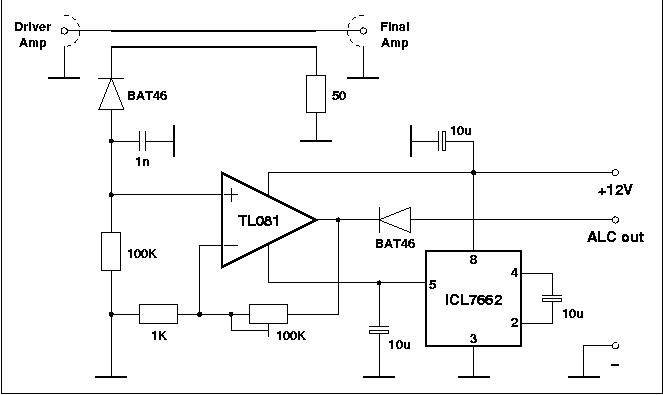
The circuit is quite similar to John's solution. In the shown circuit however, the ALC voltage is generated using a directional coupler at the final transverter output frequency. As most HF transceivers expect a negative ALC voltage (some volts) for power control, the rectified RF-voltage is also negative and amplified by a standard operational amplifier TL081. A charge pump inverter ICL7662 generates the required negative voltage. The ALC voltage and thus the output power can be adjusted by the variable 100K feedback resistor. Be aware to obtain the ALC voltage from the final amplifier's output RF- voltage. An antenna mismatch will lower the ALC voltage, maximizing the drive power and increasing the reflected power. This may unnecessarily stress your amplifier.
Comments, Suggestions: [email protected]