
DG 5 SGA
Power Inverters 12V to 230V
contents:
construction plans, technical descriptionVersion of
Nov.8th,1999Rev. 3.1
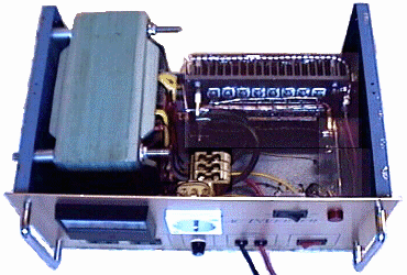
Fig. 1: 1000 VA-Inverter 12 Volt -> 230 Volt
An inverter allowes the use of 230V electrical appliances from a car battery or a solar battery. It must therefor supply a voltage that corresponds to an rms of 230 Volts sine-wave like household main supply or similar. Sine-wave voltages are not easy to generate. The advantage of sine-wave voltages ist the soft temporal rise of voltage and the absence of harmonic oscillations, which cause unwanted counter forces on engines, interferences on radio equipment and surge currents on condensers. On the other hand, square wave voltages can be generated very simply by switches, e.g. electronic valves like mosfet transistors. In former times electromagnetical switches, that operated like a door bell were used for this task. They were called "chopper cartridge" and mastered frequencies up to 200 cycles per second. The efficiency of a square wave inverter is higher than the appropriate sine wave inverter, due to its simplicity. With the help of a transformer the generated square wave voltage can be transformed to a value of 230 Volts (110 Volts) or even higher (radio transmitters e.g.).
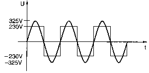
Fig. 2: Sine-wave voltage and conventional square wave voltage with both 230 Volt rms
Fig. 2 shows a sine- as well as a square wave voltage with in each case an rms of 230 Volt. In both cases an electric lamp would light with the same intensity. This is, as we know, the definition of rms. As we recognize in Fig. 2, however the peak value of the sine-wave voltage is 325 Volts, i.e. factor Ö 2 more than rms. For electric lamps this is insignificant and electric engines are appropriate for it. Electronic devices were even designed for the peak voltage of sine-wave voltage, because internally they generate DC voltage from the AC supply voltage. A condenser will be loaded on exactly the peak value of the sine-wave voltage. Electronic devices thereby usually cannot be operated on 230 Volt square wave from fig. 2. The industry nevertheless manufactured square wave inverters according to this principle in former times.
Our inverter works with a trick, to obtain the same results from square wave voltage as for sine-wave voltage.
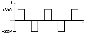
Fig. 3: Square wave voltage with duty cycle 25% for 230 Volt rms ("modified sine")
Square wave voltage in fig. 3 developes the same peak value as sine-wave voltage of 230 Volts, i.e. 230 Volt * Ö 2 = 325 Volts and nevertheless thereby obtains the demanded rms of 230 V. Square wave voltage as shown in fig. 2 (full half wave) with peak value of the corresponding sine-wave voltage would cause double amount of electrical power on electric consumers. The electrical power rises by square of voltage, and square of Ö 2 results in factor 2. The trick is, to switch the output power only for one half of every conducting cycle, thus resulting on a duty cycle of 25% on behalf of the complete oscillation period. If the calculated double amount of electric power will be generated only half the time, effective power remains the same. Industry called this cam shape "modified sine", in order to be able to differentiate the devices from conventional square wave inverters.
The inverter may feed nearly all electrical appliances, designed for 230 Volts, with exception of rotary field engines, that use condensers for generation of an auxiliary phase (condenser engines). Engines of this type are used in most refrigerators, washing machines, dishwashers and some few machine tools. Fluorescent lamps with a series inductivity to limit the operating current also won't work correctly on our inverter. This problem can be solved by increasing the duty cycle on more than 25% while decreasing the peak voltage to 275 Volts. Instead fluorescent lamps with electronics (energy saving lamps) will work very well on the inverter. There may also be problems with some small plug power supplies. An increased magnetizing current results on square wave voltages, while there would be an predominantly inductive load (cosj << 1). Duty cycle 25% and cosj =0 will result in load currents up to factor p /2 (approx. factor 1.5). But don't be confused: Cosj of most electrical appliances is between 0.8 and 1 and would be harmless.
Our inverter is suitable for:
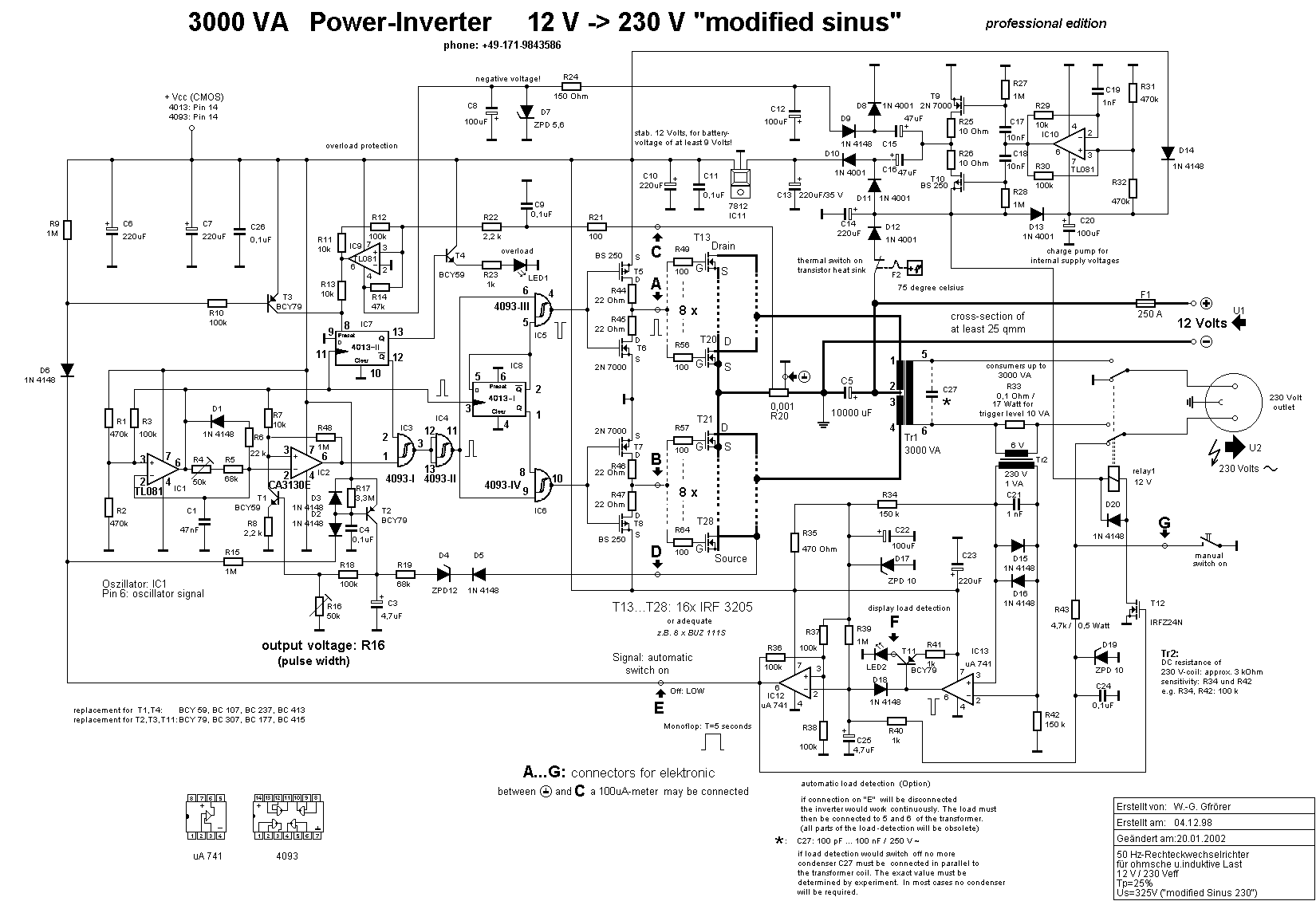
Schematic diagram:
Description of function:
The inverter chops the 12 Volt DC Battery voltage into a square wave voltage of 50 cycles per second and duty cycle of 25%, transformed by transformer Tr1 to 230 Volt rms. IC1 forms the oscillator with 100 cycles per second (120 cycles per second for 60 cycles output). Frequency is determined by C1 and the resistors R4 and R5. Resistor R6 determins the time of the flyback of the oscillator and affects likewise the frequency. In addition, R6 affects the rms of the output voltage, which must be considered if necessary, if the circuit shall be used for other frequencies. 60 cycles per second can be achieved by alignment, higher frequencies require changes in the frequency-determining parts. For high stability of frequency, special attention must be spent on condenser C1. Ceramic capacitors are not usefull, due to their high sensitivity on temperature. Most foil condensers may keep the frequency quite constant, even against strong temperature variations.
IC2 determines the pulse width and thus rms of the output voltage. The regulater consists of transistor T1, which receives its signal from the diodes D4 and D5, taken from the primary tranformer coil. The regulator adjusts the output voltage by changing the pulse width. It prevents also rising of rms on inductive or capacitive load. The characteristics of regulation can be adapted by changing D4 (important on 24 Volts applications!). Lower voltage level of D4 results in "softer" regulation, i.e. an reduction of the proportional factor.
Against earlier versions of the inverter, IC 8 now will be switched directly by the oscillator signal, thus avoiding errors by unexpected oscillations of the PWM-IC 2. Here the alternate allocation of the impulses for both transistor lines, i.e. for the positive and the negative half wave of the output voltage takes place. The final frequency of 50 cycles per second develops. Flip-flop IC7 stores a switching off instruction of the current limiter for the rest of the half wave. From the gates IC5 (4093-III) and IC6 (4093-IV), the control signal arrives at the complementary MOSFET-driver stage transistors T5/T6 and T7/T8. T6 and T7 are N-channel-enhancement mosfets and T5 and T8 are the complementary P-channel-enhancement mosfets. These transistors correspond to the well-known CMOS basic circuit (CMOS = Complementary MOS), which represents the basic of the CMOS logic family (CMOS inverters). Only the resistors R44 to R47 are new in this circuit. They provide current limitation during shifting process and protect in cases of disturbances. The control unit ist suitable for inverters up to 10 kW output power. The driver stage transistors T5 to T8 provide the signals for the power mosfets, which alternately magnetize transformer Tr1. Inductive idle currents, how they are needed e.g. by electric motors, can be returned to the battery, thanks to the integrated antiparallel recirculating diodes of the transistors. Thus they do not generate unnecessary losses, contrary to early inverters.
The most important task in our inverter is done by the mosfet transistors T13 to T28. They are connected in two groups, each of 8 transistors. They generate alternatingly the positive and negative wave of the output voltage. Each transistor line works on ist own transformer coil. After a transistor line is beeing switched off, the magnetic energy stored in the magnetic field of the transformer returns back to the battery by the integrated recirculation diodes of the second transistor line. The idle current of consumers with inductive load takes the same way. In case of strong heating up of the transistors, which should only happen on defects in the equipment, the bimetal thermal switch F2 shuts off the control electronics. In normal operation, temperature of the heat sink should be as low, that you could touch it by your hands.
The source-currents of the mosfet transistors pass over resistor R20 with the very low value of 0.001 ohms. Load currents of 100 amperes thus produces a voltage drop of only 0.1 Volt, according to an energy dissipation of 10 Watts. The electronic current limiter becomes effective for currents above 350 Amperes, i.e. on voltage drops on R20 of more than 0.35 Volts. Main cause for such high currents are short-circuits or consumers with "large" inductances, e.g. welding transformers or large battery chargers, which exhibit remanence magnetism. Also large electrolytic capacitors from switching power supplies cause immense peak currents (computer screen), just as asymmetrical load of devices with single period rectifiers or thyristor regulaters, which cause a magnetical bias to the transformer of the inverter.
The electronic overload protection by IC9 is a special feature of our inverter. It needs a additional negative supply voltage, which is produced by a charge pump, consisting of IC10 and the transistors T9 and T10. IC9 works as threshold switch (Schmitt trigger). Sensitivity can be affected by change of the value of R22. A value of 1.5 kOhm means e.g. shutdown at lower currents (for inverters with smaller power output.
While starting the inverter, the negative supply voltage from the charge pump will be missing. This leads to immediate shutdown of the power mosfets, indicated by the red LED1. Thus indefinable control signals, that could result in unwanted switching, which would force small batteries to break down, are prevented. Our inverter therefore requests no maximum or minimum battery size - it works on any 12 Volt power supply. If the electronic overload protection becomes active, a positive output signal will be present at pin 6 of IC9. Through resistor R13 the flip-flop IC7 is set, which keeps the blockage upright until the next half wave on pin 11 appeares. IC7 may be closed likewise by transistor T3, which receives its signal from the optional "load detection" . If no load is detected, the inverter will be shutdown by this circuitry in order to save battery power.
Sensitivity of the shutdown circuitry may be tested by disconnecting the lead to resistor R20 and applying variable voltages at connector "C" in the range of 0 ... 1 Volt (important: transformer Tr1 must also be disconnected!). At approx. 0.35 Volts the red LED1 would light up and would get dark again at voltages of scarcely more than 0 Volt. Parallel to resistor R20 a 100 uA measuring instrument may be attached for display of load currents.
The optional "load detection" shall not be described here in detail. It consists of the circuit parts around resistor R33, transformer Tr2, relay1 and the ICs 12 and 13. If this part of the circuit shall not be used, the inverter would work in continuous operation. Thus T3, R10, R9, D6, R15 and D3 would be obsolete. The 230 Volts load would be connected directly to clamp 5 and 6 of transformer Tr1. The "load detection" recognizes an active load by a small DC through the contacts of relay1 and resistor R43. The inverter will be switched on for approx. 5 seconds. If then a load current would appear on R33, the inverter will remain switched on, indicated by LED2 (yellow). The limitation of the output power of 3000 Watts is due to power dissipation of R33. Instead of the "amateur-solution" of R33 and Tr2, a typical current transformer may be used. Some loads do not switch on the inverter, e.g. energy-saving lamps. For this the manual activation at port "G" is intended. A small 1 VA-transformer in parallel to the energy-saving lamp would also cause a DC-current and thus would solve the problem.
Data:
Documents for download:
Schematic diagram (approx. 53 kB)
Parts list (approx. 4 kB)
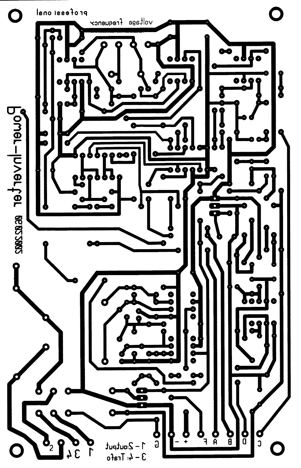
Layout for printing board (approx. 118 kB)
Complement plan (approx. 148 kB)
Transformer:
We can make the transformer by changing the windings of an old transformer.
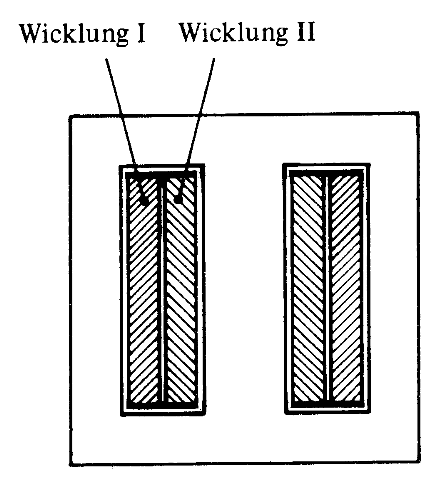
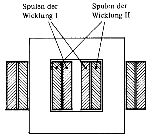
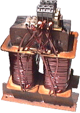
fig. 4: shell-type transformer core transformer
A transformer will provide best characteristics when the primary coil, that takes over magnetization of the iron core, fits closely around the core. For industrial transformers this would be the 230 Volts coil, on our inverters however it will be the 12 volt coil.

fig. 5: "EI"-sheet metals of a 850 VA-shell-type transformer
For the computation of the numbers of turns the following consideration applies:
The peak value of the primarily generated alternating voltage is given by the battery voltage. This determines the number of the primary windings of the transformer. On the secondary side of the transformer likewise the peak value must be taken also for computation, i.e. 325 Volt. In the case of a fully loaded battery the supply voltage of the inverter amounts to 13.8 Volts. The peak value of the 230 Volts output voltage may not exceed that of the usual supply networks, even if the rms could be held on 230 Volts by reduction of the duty cycle. The following table for the output voltage results (without pulse width regulation):
|
Battery voltage |
Upeak (secondary) |
Urms (secondary) |
|
11,8 Volt |
297 Volt |
210 Volt |
|
12,35 Volt |
311 Volt |
220 Volt |
|
12,7 Volt (accord. 9 Vrms |
320 Volt |
227 Volt |
|
12,9 Volt |
325 Volt |
230 Volt |
|
13,5 Volt |
340 Volt |
240 Volt |
The table applies to fixed duty cycle of 25% and/or sine-wave voltage and without consideration of the magnetization energy. Our inverter will keep the output voltage constant on an rms of 230 Volts, due to its pulse width regulation, even if the peak value will drop or rise, due to the battery voltage. The peak value will not exceed 350 Volts (247 Vrms for sine-wave voltage), critical for electronics, even in case of fully loaded battery. Theoretical, without pulse width regulation, the rms could rise again up to the theoretical factor of 2, according to a duty cycle of 50%, because of the magnetization energy. The recirculating magnetization energy already forms the beginning of the next half wave of the output voltage (see fig. 6). But without load there is no rms by definition, so this consideration is only of theoretical nature, with one exception: A measuring instrument, calibrated on rms would indicate a wrong output voltage and small consumers, who need less than the magnetizing energy of the transformer, could get damaged.

fig. 6: output voltage with no load or inductive load
The table shows, that the transformer needs a ratio of windings of 1 : 25. The schematic diagram shows, that it has two primary windings and one secondary. Both primary windings have the same number of turns and the secondary winding must have by factor 25 more turns (110 Volts: factor 13).
Here a selection of used transformers:
|
Length |
Width |
Deep |
Power |
Primarily |
Secondary |
idle current |
|
150 mm |
125 mm |
50 mm |
460 VA |
2 x 13 W |
325 W |
1,4 Ampere |
|
150 mm |
125 mm |
50 mm |
460 VA |
2 x 14 W |
350 W |
1,2 Ampere |
|
150 mm |
125 mm |
67 mm |
600 VA |
2 x 10 W |
250 W |
2,2 Ampere |
|
150 mm |
125 mm |
67 mm |
600 VA |
2 x 11 W |
275 W |
1,6 Ampere |
|
150 mm |
125 mm |
67 mm |
600 VA |
2 x 12 W |
300 W |
1,4 Ampere |
|
150 mm |
125 mm |
95 mm |
1000 VA |
2 x 9 W |
225 W |
1,4 Ampere |
|
|
- |
- |
2000 VA |
2 x 11 W |
275 W |
2,2 Ampere |
|
170 mm |
140 mm |
80 mm |
850 VA |
2 x 12 W |
300 W |
1,5 Ampere |
|
170 mm |
140 mm |
75 mm |
850 VA |
2 x 13 W |
325 W |
1,3 Ampere |
|
175 mm |
140 mm |
60 mm |
750 VA |
2 x 13 W |
325 W |
1,2 Ampere |
Length: length of the "I" from fig. 5
Deep: thickness of pile of all iron sheet metals
Power: rated output
The table shows, that the number of turns is not particularly critical. Only the ratio of primary windings to secondary must be correct. The rms of the output voltage will be finally adjusted by the automatic controller with R16 to the value of 220 or 230 Volts. It is of great importance however, that both primary coils are absolutely symmetrical. They must be wound bifilar, so that they are very close to each other. While one winding will magnetize the core, the corresponding winding will return the magnetizing energy. If there is no close coupling of both primary coils, energy losses will result by overvoltage, causing avalanche effects on the transistors. Despite completely symmetrical structure of the windings, the transformer will show a small magnetical bias (DC biasing), recognizable from the asymmetrical magnetizing currents, which can be watched on R20 with an oscilloscope. This biasing will change on every change of load, in particular with strong inductive loads. This effect is completely normal for square wave voltages at inductances and is connected with the heavy non-linearity of ferro-magnetical materials. The second half wave of the output voltage applies other magnetizing conditions to the ferro-magnetic transformer core due to the remaining remanence. (only with sine-wave voltages an equilibrium can adjust itself after several oscillations, due to hysteresis losses, see "Rush effect"). Critical unbalances, which develop e.g. after an impact short-circuit, are eliminated surely by the electronic shutdown system.
Wire strength:
Current densities from 3.5 A/mm2 to 4 A/mm2 are used on industrial transformers. If our inverter is not beeing used excessivly, current densities may even be higher. A transformer with 1000 VA needs approx. 84 ampere from the 12 Volt battery on nominal load. Since the two primary coils alternate mutually, we may count from 42 amperes. (This is strictly not correct, since the acceptance applies only if both windings would exhibit double surface for heat emission). For a round wire this would mean a diameter of 4 mm. Such wire is hardly to wind, also automats can't do it perfectly. A solution may be wires with rectangular cross section or several smaller wires in parallel.
After winding the transformer, the sheet metals must be inserted again. With each layer we change the direction of the sheet metals, while in the original condition several sheet metals were probably summarized into packages, in order to increase the air gap and linearize magnetizing currents. This effect isn't needed for our inverter. Magnetizing currents are always extremely nonlinear in square wave transformers, and they are asymmetrical also. This has no effect on the performance of the inverter and the output voltage.
After the transformer has been built, it should first be tested. Therefore we attach its 230 Volts windings to public electricity mains or any other 230 Volts source. Each low-voltage coil should now show 9 Volts. Now we can connect the beginning of one "primary" coil with the end of the other. At the free ends a voltage of 18 V now should appear. If this voltage would be 0 V, the windings have been connected the wrong way.
The making of a transformer is a very laborious work. Nobody likes to take a transformer apart for a second time to correct the windings. With unknown transformers it is advisable to apply first a sample coil of thin and easy to handle wire and test the power input on idle. The windings of the sample coil can be changed without dividing the transformer. For this test the transformer does not need the secondary 230 Volts coil. Only the electronics must be adjusted correctly (tested with another, correct transformer or an oscilloscope: duty cycle 25%).
Transforer computation:
For the first regard, it appears difficult to seize the obscure and for precisive computation not accessible magnetization procedures in the magnetic core of a transformer. I want to show, that in our case this is not necessary. As the table with the numbers of turns shows, a tranformer may be built on different numbers of turns, only the relation to each other must be exact.
We specify the maximum magnetic induction on a value of 1.5 Tesla. For computation now only two simple equations are necessary:
|
Uind=induced voltage |
n =number of turns |
|
F = magnetic flux |
t =transistor switch-on time |
|
B = magnetic induction |
A =cross-section area of transformer core |
For power electronics resistive load shall not calculate on energy conversion. Thus the whole battery voltage will apply on the transformer coil for the whole switch-on time of the transistor. The switch-on time results in 5 milliseconds, dependend on the period of the 50 cycles / second oscillation and a duty-cycle of 25% (period of a 50 cycle oscillation is 1 / 50 Hz = 20 milliseconds).
Sample calculation for the above described 850 VA transformer:
The cross-section area of the transformer calculates to A = 60 mm x 80 mm = 4,8 x 10⁻³ m2
|
Uind = 12.7 Volt |
B = 1.5 Tesla = 1.5 Vs/ m2 |
|
t = 5 ms |
A = 4.8 x 10⁻³ m2 |
With equation 2) the magnetic flux calculates to F = B x A = 1.5 Vs/ m2 x 4.8 x 10-3 m2 = 7.2 x 10⁻³ Vs
set in equation 1') results
Number of turns n=Uind x t/F = 12.7 V x 5 x 10-3 s / (7.2 x 10⁻³ Vs) = 8.82 (rounded up 9 turns).
By trying I built the transformer with 2 x 12 turns. The losses were clearly smaller thereby. The calculated flux in this case was only 1.1 Tesla.
High load resistor R 20:
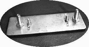
fig. 7: resistor 0,001 Ohm made of high-grade steel sheet metal
Resistor R20 takes up the whole load current of the inverter and thus enables the electronic shutdown circuit by evaluation of a small voltage drop. I was very astonished to learn, that different steel grades had different electrical resistance. High-grade steel exhibited a 2.5 higher resistance than conventional steel and that's why I used it. The data for other steel type may differ, so here what I experienced:
value of the resistor: 0,001 ohms
length: 110 mm
Width: 40 mm
Thickness: 1 mm
Distance of the screws for load current: 80 mm
Diameter of screw connections: 6 mm
Distance of solder taps: 55 mm (actual measuring section with 0,001 ohms!)
The actual value of the resistor between the screw connections is little more higher than between the solder taps, the actual measuring section. At the solder points additionally a small 100 uA panel meter may be attached.
Alignment of the resistor:
For an unknown steel grade or the desire for particularly high accuracy of the resistor value an alignment with a defined examining current is recommendet, e.g. by a car lamp at the lab power supply unit. The load current would be adjusted to e.g. 5 amperes. Now we may find with the test prods of a sensitive millivoltage measurement instrument those two points on the resistor, for which the voltage drop will be U= I * R = 5 A * 0,001 Ohm = 5 mV. These points would be marked by a felt-tip pen. At these points the solder taps will be fixed by screws.
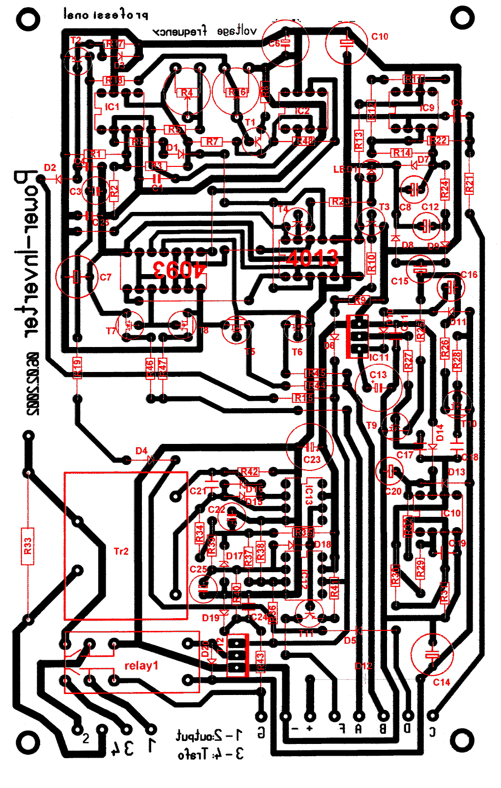
Control electronics:
The use of a pre-drilled print board is most comfortable. In the past most inverters have been built on strip hole plates, in small-batch manufacturing.
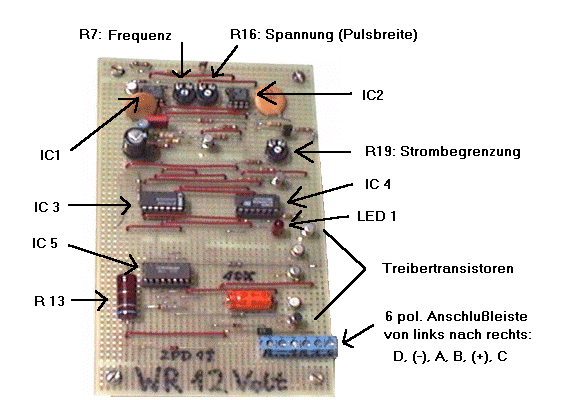
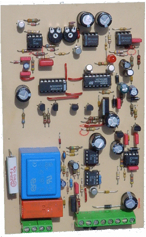
fig. 8: control electronics on strip hole plate (previous version) and PCB of the "professional edition"
Assembly of the mosfet-transistors on the heat sink:
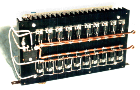
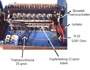
fig. 10: heat sink, mosfet transistors, connections
Testing:
MOS-FET-transistors:
The transistors on the heat sink may be tested while they are not yet connected to the transformer and the control unit. First we touch with one hand the source connections of the transistors and with the other the gate connections. This will discharge the gates. Now the source / drain connections must behave like a diode, which we can test with an ohm meter. For the next test we connect a car lamp between the drain connections of the transistors and the positive pole of a battery. The negative pole will be connected to the source of the transistors. The gate must be open. If we now touch with one hand the positive pole of the battery and with the other the gates, the lamp will light up. Now we touch the negative pole of the battery and simuntanously the gates and the lamp will be switched off. If this test is positive, the transistors are o.k.
Control unit: For testing the control unit, clamp "G" and clamp "C" must be connected to ground (minus pole). This prevents the load detection circuit from switch-off. The outputs "A" and "B" will show an output voltage between 3.5 and 4 volts. Theoretically the exact value should be 2.5 volts, according to a duty cycle of 25%, but the transformer is not yet connected and so the pulse width regulator will generate maximum value. If a frequency counter and an oscilloscope are available, the control signals may be checked and adjusted to 50 cycles or 20 milliseconds (period of the 50 cycle oscillation) at these outputs. During normal operation the transformer generates peak voltages up to 28 volts on clamp "D". The pulse width regulator may be tested, if variable DC voltages from 12 V to 28 V will be applied to this connection. For testing the current limiter, variable DC voltage may be applied to clamp "C" (0 ... 1 Volt). The switch-off should take place at about 0.35 volts.
The control unit may also be tested in connection with the mosfet transistors. Instead of the transformer, autolamps would be connected. The brightness of the lamps may now be adjusted by turning resistor R16 or connecting a DC voltage to clamp "D" as described above.
The autolamp also makes possible a very simple test to adjust the frequency. Therefore we put in series with the lamp the 12 volts output of a small tranformer, connected primarily to the mains supply. Both alternating voltages will now be added or subtracted, dependent on the phase shift. The lamp will flicker. The goal is, to make this flickering very slowly. Attention: The autolamp must be 24 volts or two lamps in series.
Final assembly:
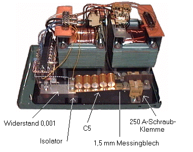
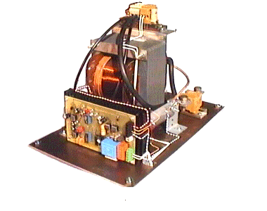
fig. 11: 1500 VA inverter with 2 parallel transformers and 1000 VA inverter
--------------------------