DL4YHF's Homebrew Homepage:
|
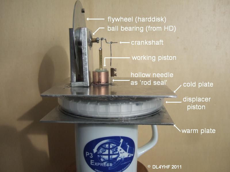
Homebrew low-temperature Stirling motorInspired by a 'Coffee Cup Stirling Motor' seen on the internet, something similar had to be built - just for fun. Of course it had to be a low-power design (which is what 'QRP' stands for). Here is a video of the 'DL4YHF QRP Stirling' (right-click and "save as", then play it in your favourite video player, because most web browsers don't recognize the file extension 'mp4' and try to show the *.mp4 file as text). Main parts :
Photo of the assembled motor prototype on a coffe pot (supported by AMSAT-DL, hi) ...
Stirling motor details :
The sliding seal for the displacer piston (on the right side of the image above) is a hollow needle from an insulin syringe, with an inner diameter of about 0.6 mm. This perfectly matches the outer diameter of an ordinary needle (standard pin, Stecknadel) - it's almost airtight, but the needle perfectly slips inside the hollow needle (it moves down by its own weight, even without oil for lubrication). Of course both must be precisely straight - the slightest bend, and the motor won't work because of friction. If you decide to build a similar motor 'from trash' :
"Hacking a harddisk for ball bearings"
Remove the HD's sealing tape, open the housing, remove the ceramic hard disks
(carefully) and the head assembly. Then remove the disk motor, which contains
the ball bearings.
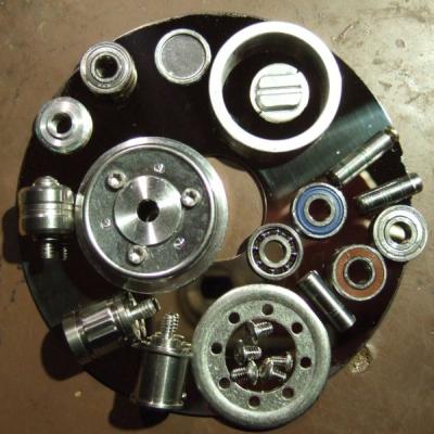
Hint: Like the author of this text, you will most likely not have a suitable screwdriver for the exotic 'harddisk screws'. But they can be loosened with a side cutter - hold the screw head tight, and turn the screw with the cutter. Ugly, but it works ! In some cases, you can separate the motor's stator and rotor after peeling off a seal (bluish glue) at the bottom of the motor, and gently knocking on the center of the shaft in the center. Don't use too much force with the hammer, you may easily ruin the ball bearings. Two typical seals (small round caps, made of steel or aluminium sheet metal) are shown in the upper part of the photo. One motor in a 3.5" harddisk contains two ball bearings, usually with 13 mm outer diameter, and 5 mm inner diameter like the ones shown above.
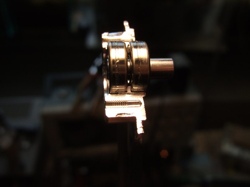
Usually, you will need to cut the motor (the part with the bearings) into
two halves with a hack saw, because the two ball bearings are pressed in
from opposite sides into the aluminium turned part. There often is a small
division bar between the two bearings (visible on the photo below), making
it impossible to "hammer them out" to wards one side. Thus, carefully use
the hack saw. Afterwards, carefully remove aluminium saw dust from the bearings
! Here is a photo of the hacked motor, before removing the bearings. This
is the rotor (once the 'moving part'), a round object made of aluminium which
originally held one or two ceramic hard-disk in place, using three or four
screws.
Note: Because the aluminium is much softer than the steel of the ball bearings, you will 'feel' when the hacksaw touches the bearings - time to stop then. Make two cuts from opposite sides. After that, use a chisel or similar object to break up the two parts. This is the step at which the above photo was taken. The original shaft (made of steel) can be carefully 'hammered out' of the ball bearings in a vise. Use a flat washer with 5 mm inner diameter placed underneath the bearing to avoid damaging the bearing by the hammer strokes. Don't hold the outer part of the bearing in the vise, while applying force to the steel shaft in the center !
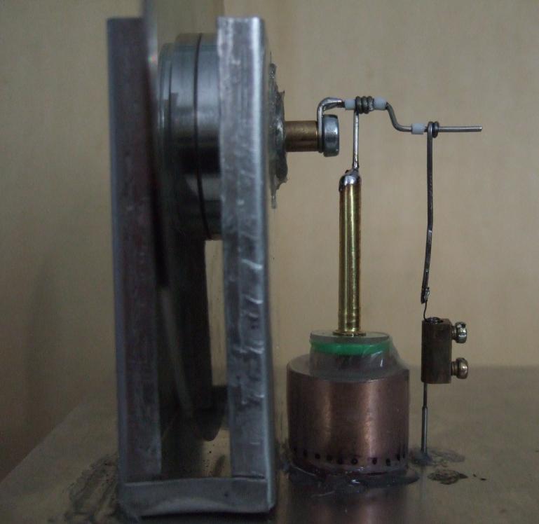
I used a 5 mm shaft made of brass, because it can be soldered if necessary,
or cut an inner thread into it. This is how the crankshaft is mounted see
the 2nd photo further above: It is simply screwed to one end of the 5-mm
shaft. |