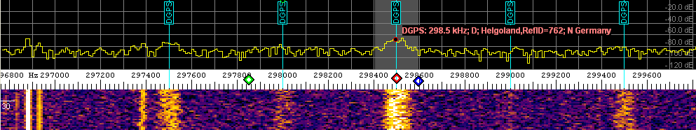
In the main spectrum display, the MW DGPS beacon band may look like this, including the frequency markers to "tune" the filter:
For some 'DX' reception tests with DGPS beacons, a crude DGPS decoder (actually, RTCM SC-104 V2.x) was implemented in Spectrum Lab .
MSK is in worldwide use for DGPS beacons on medium wave (near 300 kHz). This document describes how to use Spectrum Lab for DGPS reception on medium wave.
Even though the MSK-demodulator performs its own passband filtering, it helps to use additional passband filtering before the signal enters the decoder:
For 100 baud DGPS beacons, use a passband width of 120 Hz or so (to avoid
phase distortions or "ringing", especially at the edges of the passbands).
For 200 baud DGPS beacons, use something like 240 to 500 Hz (depending on
the filter actually used; be generous with analog filters).
If you use a soundcard for input, and your MW receiver only has "wide" filters,
try this one:
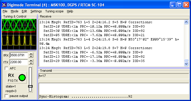
The digimode terminal can be activated from SpecLab's main menu ('View/Windows') or from the component window. The DGPS decoder can be activated by selecting one of the "preconfigured" settings, or configured for your own needs as explained in the steps further below.
Simple method (using a preconfigured setting) :
Alternative (without using the preconfigured settings) :
If all works ok, and the receiver is properly tuned to a DGPS beacon, with sufficient signal-to-noise ratio, decoded messages will now be displayed in the "Receive" part of the digimode terminal. Since you will never transmit DGPS messages with this program, you can reduce the size of the 'Transmit' area of the window by moving the splitter down.
Details on the format of the decoded messages follow in one of the next chapters.
To check the MSK demodulator, the author tried to receive some European DGPS beacons on medium wave. Many of those beacons (like the Zeven DGPS transmitter on 303.5 kHz) use 100 bit/second, so the 'symbol rate' in the digimode configuration dialog must be set to 100.0 symbols/second (here, the same as 100 bit/second).
Occasionally check the eye pattern on the tuning sope. Zero crossings of the green line should only happen between two bit slots, and the "peaks" coinciding with the vertical grid (each vertical line in the grid indicates the center of a bit slot; not the separation between two bits). The red curve shows the envelope, which should be almost a flat line (for MSK). There may also be a yellow curve (depending on the MSK demodulator in use) which shows the bit synchronisation clock.
(eye pattern of a properly tuned MSK signal)
By default (following the setup in the previous chapter), the decoder will print "human readable" text, if it can decode anything at all. It if doesn't (for example, because the signal is too weak, distorted, mistuned, wrong bitrate, etc..), check the eye pattern again, and switch to a different output format. For example, the "binary" or "debug" format allows you to see the raw bits pouring out of the demodulator (not the decoder).
To select between different formatting options (for the decoded output), select Settings .. Advanced Settings in the terminal's menu, and set the Rx Character Display option to Translated (type 1) or Translated (type 2). 'Type 1' will show the DGPS signal as 30-bit GPS words, with an indicator for the parity check (*=parity check ok, -=parity check failed). 'Type 2' may present the output in a different format, which wasn't clear at the time of this writing yet.
The 'Debug' character display modes are subject to frequent change; for that reason they are not explained here. Most likely, the debug modes will show a binary, or hexadecimal output if the decoder cannot convert the message into plain text.
In the normal (default) character display mode, received DGPS messages will be displayed as plain, human readable text. In this mode, the decoder doesn't print anything if he doesn't decode valid DGPS messages. The Receive window will be filled with something like this (more about the display formats in a later chapter) :
Msg9: RefID=763 L=5 Z=14:Ø4.8 S=Ø H=Ø Data=
Ø6FD86 Ø53615 FE69Ø4 ØE1ØFE 94Ø551

Msg9: RefID=763 L=5 Z=14:Ø7.2 S=1 H=Ø Data= ØAFCF9
Ø36E1E FBDAØ4 58Ø5FE 13Ø35A

Msg9: RefID=763 L=5 Z=14:Ø9.Ø S=2 H=Ø Data= 1FFEØ5
FDØ8ØD FBEØFF 2Ø1DFE BEFD21

Msg9: RefID=763 L=5 Z=14:12.Ø S=3 H=Ø Data= Ø6FD8B
Ø73615 FE6CØ5 ØE1ØFE 96Ø551

Msg9: RefID=763 L=5 Z=14:13.8 S=4 H=Ø Data= ØAFCFB FF6E1E FBDDFB
58Ø5FE 17FE5A

Msg9: RefID=763 L=5 Z=14:16.2 S=5 H=Ø Data= 1FFEØ8
Ø6Ø8ØD FBE2Ø8 2Ø1DFE CØØ721

Msg9: RefID=763 L=5 Z=14:18.Ø S=6 H=Ø Data= Ø6FD8E
ØE3615 FE6FØD ØE1ØFE 98ØD51

Msg9: RefID=763 L=5 Z=14:19.8 S=7 H=Ø Data= ØAFCFA FD6E1E FBDFFE
58Ø5FE 19FD5A

Msg9: RefID=763 L=5 Z=14:22.2 S=Ø H=Ø Data= 1FFEØ9
F7Ø8ØD FBE1F5 2Ø1DFE C1F721
Like in the above example, most DGPS becons use message type 9 to send DGPS correction date. For medium wave DXing, the "RefID" is the most important output of the decoder, because you can see that 'BC Reference ID' in many beacon lists, for example the ones at www.ndblist.info/datamodes.htm .
See also: DGPS decoder output formats .
The sync histogram is displayed at the bottom of the terminal window, as
long as the RTCM decoder is active.
It is a quality indicator for the decoder's ability to synchronize to the
received stream of 30-bit GPS words, by virtue of the six parity bits in
each word.
Sync-Histogram: ..1..............1.9.1........ |
To understand the sync histogram, it's important to know a little bit about the bit transport layer used by the MF DGPS beacons.
Without going too much into the details here, the official standard for the bit transportation layer is explained in a document titled
NAVSTAR GLOBAL POSITIONING SYSTEM
Interface Specification
IS-GPS-200
Revision D
7 December 2004
All messages are packed into 30-bit words, as explained in Chapter 20.3.5 of IS-GPS-200 .
After each received bit, the decoder (as implemented in Spectrum Lab) checks the parity as explained in IS-GPS-200 Table 20-XIV, as if a 30-bit word was complete. If the parity check fails, a counter for the current bit slot (out of 30 possible bits) is decremented, otherwise incremented. Each of the 30 counters is limited to a range of 0 to 9.
After each received bit, the decoder also searches for the larget value in the array of 30 counters. The counter with the largest value will most likely be the one which marks the end of a 30-bit word, because this bit slot has the largest number of successfull parity checks. Since there are only 6 parity bits in each 30-bit word, even with purely random noise at the input, there is still a chance of 1 out of 64 (= 2 power 6) to get "successful" parity checks.
Now the 'Sync Histogram' simply shows the values of those 30 counters (one counter per bit in the 30-bit GPS word). For better visibility, counter values of zero are displayed as dots. Since the maximum counter value is limited to 9, this is the best (largest) value which can appear in the sync histogram.
Due to the 1/64 chance of false "successfull" parity checks, even with a perfect input signal, the sync histogram will show occasional 'ones' besides the main peak (9). Don't worry about that. More important is that the 'main peak' in the sync histogram reaches at least 5, but ideally 9. The decoder starts outputting decoded messages at a peak value of 3, but such a bad parity ratio will sometimes produce garbage.
The absolute position of the main peak in the sync histogram doesn't matter - it depends solely of the time when the demodulator emitted the first data bit to the decoder, which is purely random. If the position of the sync peak moves left or right (within the 30 possible positions), there may be something wrong with the soundcard (lost input samples), or too large CPU load (also causing a loss of samples), or a soundcard sampling rate which is too far off the nominal value. To cure the latter, try to "calibrate" the sampling rate as described here.
The output format (displayed in the receive window) depends on the Rx Character Display setting on the 'Advanced Settings' tab of the digimode control panel.
This can be one of the following:
The following tokens are used to display the common header for all DGPS message types:
The following tokens are message specific, and are only used in the 'verbose' output formats:
In the default 'verbose' format, the decoder output may look like this:
(If the slash-zero ..Ø.. looks too ugly,
turn it off in the digimode terminal configuration under Advanced
Settings..)
Msg9: RefID=763 L=5 Z=ØØ:27.Ø S=5 H=Ø
Corrections:("Gridle"?? where's that ;o)
SatID=13 UDRE:<1m PRC=-2Ø.34m RRC=-Ø.Ø16m/s
IOD=55
SatID=23 UDRE:<1m PRC= -7.52m RRC=-Ø.Ø2Øm/s
IOD=59
SatID=11 UDRE:<1m PRC= -6.2Øm RRC=-Ø.Ø2Øm/s
IOD=45
Msg3: RefID=76Ø L=4 Z=17:15.Ø S=1 H=6
N5Ø°2Ø'Ø1.9" EØØ7°38'22.2"
h=377.2m
Msg3: RefID=761 L=4 Z=ØØ:15.6 S=Ø H=Ø
N54°22'28.Ø" EØ12°56'Ø2.4" h= 49.4m
Msg3: RefID=762 L=4 Z=3Ø:15.6 S=1 H=Ø
N54°1Ø'59.Ø" EØØ7°54'42.Ø" h=
52.4m
Msg3: RefID=764 L=4 Z=15:15.Ø S=6 H=Ø N48°49'48.8"
EØØ8°Ø6'41.5" h=18Ø.8m
Msg3: RefID=72Ø L=4 Z=45:21.6 S=5 H=Ø N56°26'37.6"
EØ15°39'19.8" h=156.9m
Msg3: RefID=686 L=4 Z=45:15.6 S=3 H=Ø N57°Ø8'2Ø.4"
WØØ2°Ø2'54.8" h=1Ø8.7m
Msg7: RefID=426 L=3 Z=Ø5:Ø7.8 S=6 H=Ø Beacon Almanac:
BcastID=426 Freq=3Ø2.ØkHz Pos=N51°36'28"
EØØ4°55'18" 2ØØ bit/sec MSK async
Msg7: RefID=762 L=6 Z=3Ø:15.Ø S=2 H=Ø Beacon Almanac:
BcastID=491 Freq=3Ø8.ØkHz Pos=N54°22'56"
EØ12°55'49" 1ØØ bit/sec MSK async
BcastID=492 Freq=298.5kHz Pos=N54°11'24"
EØØ7°54'35" 1ØØ bit/sec MSK async
Msg7: RefID=763 L=12 Z=55:16.2 S=2 H=Ø Beacon Almanac:
BcastID=761 Freq=3Ø8.ØkHz Pos=N54°2Ø'28"
EØ12°21'53" 1ØØ bit/sec MSK async
BcastID=762 Freq=298.5kHz Pos=N54°11'24"
EØØ7°53'56" 1ØØ bit/sec MSK async
BcastID=763 Freq=3Ø3.5kHz Pos=N53°17'2Ø"
EØØ9°15'ØØ" 1ØØ bit/sec MSK
async
BcastID=493 Freq=3Ø2.5kHz Pos=N5Ø°22'18"
EØØ7°34'49" 1ØØ bit/sec MSK async
Msg16: RefID=761 L=1Ø Z=ØØ:15.6 S=1 H=Ø RS Gross
Mohrdorf Testbetrieb
Msg16: RefID=762 L=8 Z=ØØ:15.6 S=2 H=Ø RS Koblenz
Testbetrieb
Msg16: RefID=763 L=8 Z=ØØ:15.6 S=3 H=Ø RS Zeven Test
Operation
Msg16: RefID=764 L=9 Z=ØØ:15.Ø S=3 H=Ø RS test
betrieb monitored
Msg16: RefID=686 L=8 Z=Ø1:ØØ.Ø S=3 H=Ø
Gridle under maintenace
Msg16: RefID=851 L=9 Z=11:Ø8.4 S=3 H=7 Beacon Obristvi under test
Message 7, the beacon almanac, sometimes lists a few beacons in the neighbourhood
of the station which sent this message.
In the verbose output modes, the decoder emits a new line for each listed
reference station, including the 'broadcast ID' (see note on this below),
the position in WGS-84 format (or ECEF coordinates), the frequency, beacon
range, and possibly some information about the bitrate and modulation.
Some beacons do not send info about their 'neighbours' as you can see in
the examples above.
(Note that some beacons identified themselves itself with the
same value for the "Broadcast ID" and the "Reference ID".
By the time of this writing it was not totally clear why, because other beacons
show different values in message 7).
For the medium wave DXer, the 'Reference ID' (short: RefID) is probably the
most important parameter. Fortunately this parameter is contained in the
header of each message, and thus listed many dozen times per minute.For other
users, it may be more interesting to catch only message types 3 (GPS Reference
Station Parameters), 7 (DGPS Radiobeacon Almanac), or 16 (text messages).
To achieve this, open the digimode configuration again, switch to the
Decoder Specific tab, and enter the message type number to
reject there.
To test the decoder "off-line" (using 'raw' demodulated, but neither synchronized nor decoded bits), use the 'raw bit' file analysis mode described here.
You can use any plain text file which only contain 'ones' and 'zeros' (in ASCII) to let any previously recorded bitstream run through the decoder, and watch the decoder's output in the RX window.
Up to now, the following functions have been implemented in SpecLab's
interpreter to access the output of the decoder.
The purpose of these functions is to plot the PRC values in the
watch/plot window.
< ToDo: Complete this ... >
See also: main index, GPS (NMEA-0183) decoder .
Last modified: 2009-11-15 (YYYY-MM-DD)