DL4YHF's Homebrew Homepage:
|
High Voltage nonsense (experiments with no serious purpose)
Having build several Tesla transformers (spark gap and "solid state")
and oscillators with TV flyback transformers with 2N3055 transistors
some decades ago, I wondered about the efficieny obtainable with
modern MOSFETs in a zero-voltage switching configuration (ZVS).
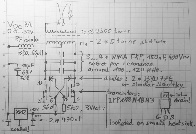
A very simple but efficient configuration is the
Baxandall
oscillator (which LOOKS similar like a Royer oscillator,
but the principle is different. A Royer oscillator's frequency
depends on core saturation, a Baxandall oscillator uses a resonant
tank as the primary).
For such a simple circuit as the Mazzilli Converter, the power efficiency is suprisingly good. The MOSFETs remained cold, the only losses occurred in the gate pull-up resistors (56 Ohms in my case, since I wanted a fast voltage rise on the transistor gates) and in the tank capacitors (3 * WIMA-FKP 150 nF in parallel). Also (but this was expected) the old TV transformer's high voltage secondary coil (without internal diodes as seen in "modern" TV flyback transformer) got a little warm after a 10-minute run driving the Jacob's ladder. The secondary coil had approximately 2600 turns (calculated from the measured voltage ratio between primary and secondary), and a DC resistance of 1 kOhm. You don't want to push 0.1 amps (for a really hot arc) through such a coil, so how to turn this beast into 'Frankenstein Monster Lab' equipment ? A different secondary with a similar number of turns but a significantly lower loss resistance was needed. A nice effect can be achieved by covering the electrodes of the Jacobs Ladder with a solution of salt - the sodium chloride gets atomized by the arc, and the sodium gives the flame an intense amber colour:
Other flame colours can be achieved by covering the electrodes with Strontium chloride (intense red) or copper chloride (green), but this is definitely not recommended for indoor operation. The current in the 'TV flyback' secondary caused it to heat up quickly, so this isn't good for a 'permanent' installation. To make the transformer suitable for unattended operation with 100 percent duty cycle, without fearing a 'secondary melt-down', a homemade secondary was planned. ... to be continued - or not :o) ... |
