How to complete the kit:
Important note: You are handling sensitive devices here!
Ok, let me say they are not so sensitive, lets compare them to standard computer parts. I never destroyed a device at all.
Take care on electrostatic discharge, don't user plumber tools
and if you have doubts, ask someone in your neighbourhood for help.
Completing the kit is not complicated and I need about 30min for one. So better take help from someone who knows how to handle
these kind of parts instead doing it by yourselfs. If nothing helps and
if you are using a directly mains connected soldering iron, disconnect
it from the mains each time you solder. Taking care this time is
surely worth the result.
Please also note that there are some pictures about what to do for the extra miniADSB installation on its own page.
And finally remember that there are also some solder bridges, which
I set up for USB operation prior to delivery. If you need others like
the Lantronix Xport or the BTM-222 Bluetooth, please read the bottom of
the jumpers page.
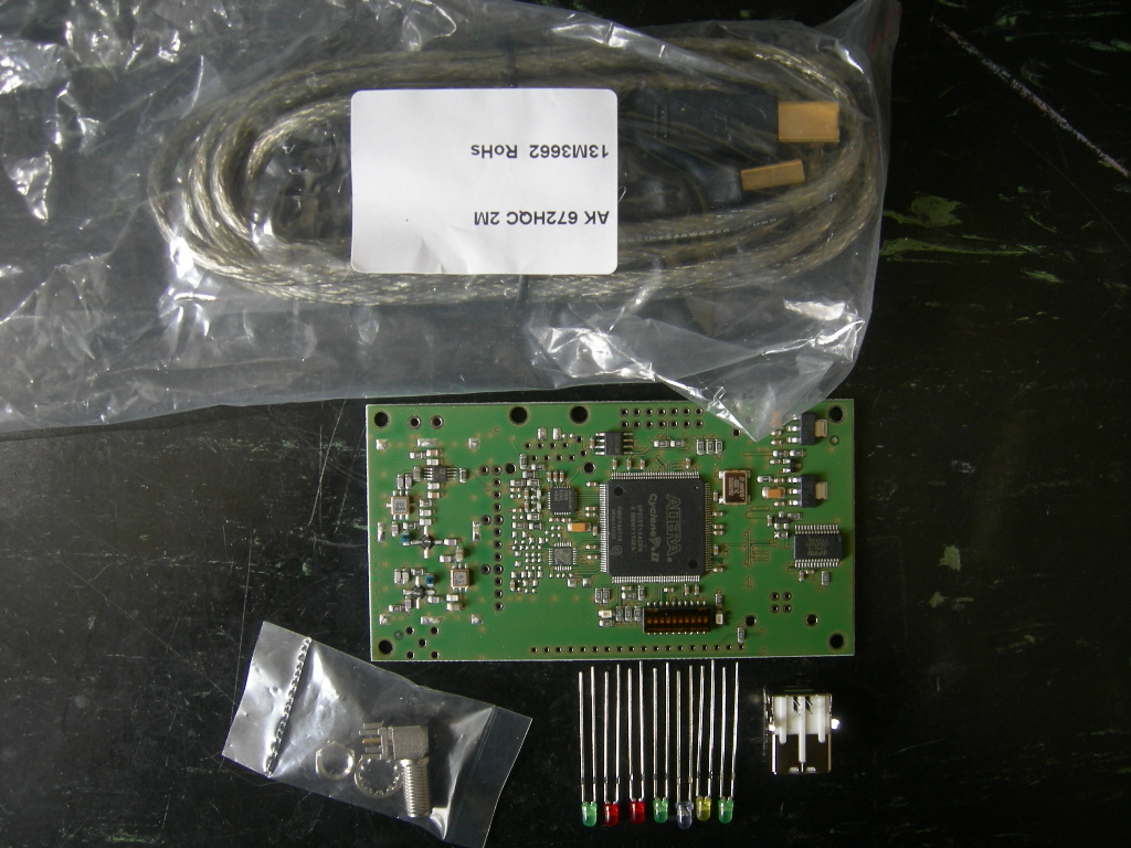
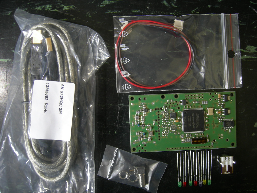
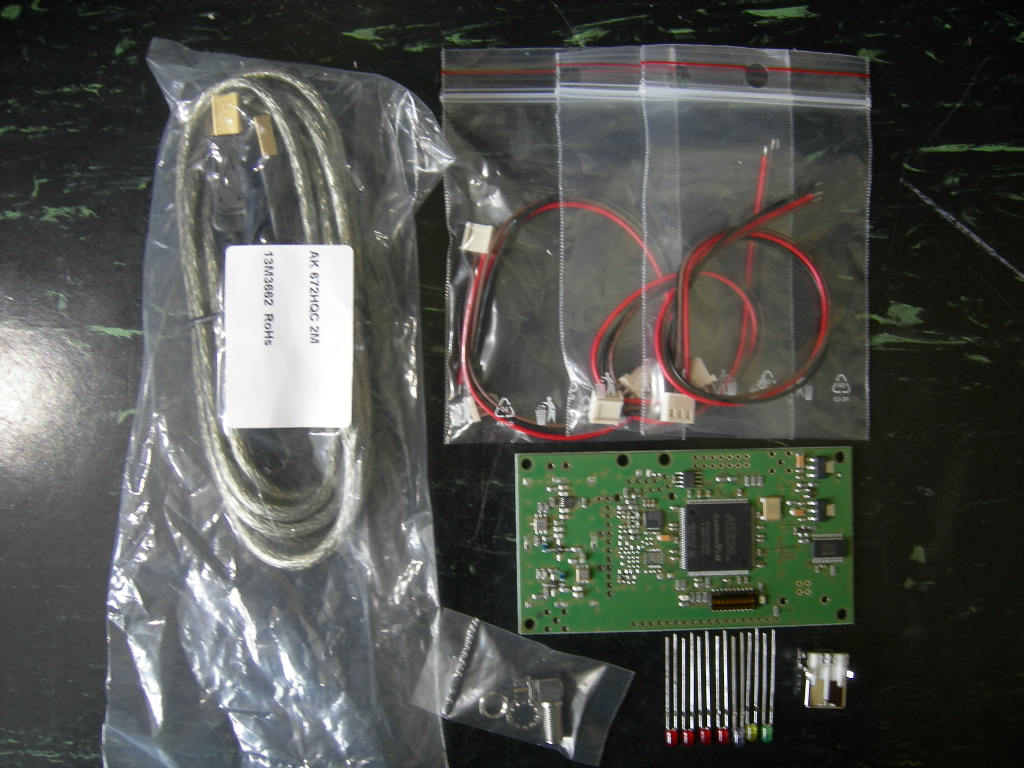
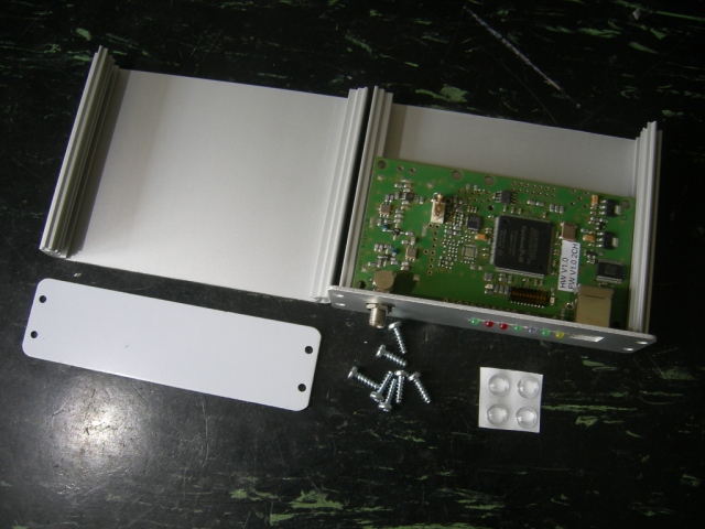
The kit contains different parts depending on the version you've ordered:
|
1 Channel Version
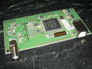
1 SMD-preassembled board "Mode-S Beast"
1 right angle female SMA connector
3 green LEDs
2 red LEDs
1 blue LED
1 yellow LED
1 USB Type B female connector
1 high quality USB cable
|
2 Channel Version

1 SMD-preassembled board "Mode-S Beast"
1 right angle female SMA connector
3 green LEDs
2 red LEDs
1 blue LED
1 yellow LED
1 33 Ohm standard resistor (not shown)
1 3pin cable for miniADSB (*1)
1 USB Type B female connector
1 high quality USB cable
|
4 Channel Version

1 SMD-preassembled board "Mode-S Beast"
1 right angle female SMA connector
1 green LEDs
4 red LEDs
1 blue LED
1 yellow LED
3 33 Ohm standard resistors (not shown)
3 3pin cable for miniADSB (*1)
1 USB Type B female connector
1 high quality USB cable |
(*1) Please swap the brown and red wire as shown on the miniADSB page.
I decided to deliver an USB cable as well because
a) some might not have such available and
b) I did see that cheap or scrappy USB cables decrease the performance.
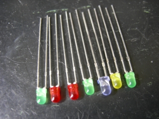
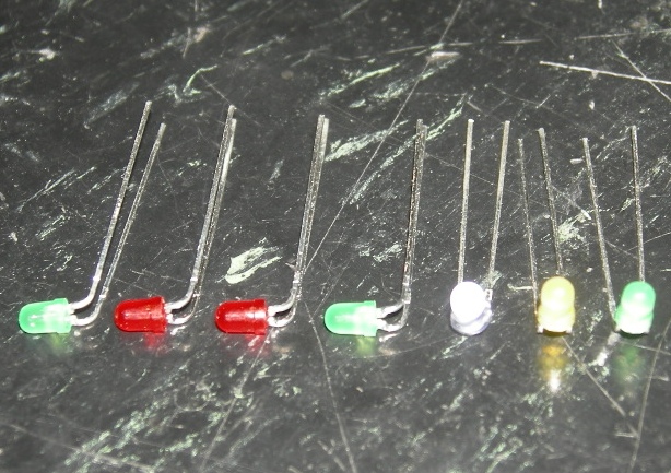
First, you start with the LEDs:
|
All LEDs do have their cathode
to the left side when seen from the front panel. Cathode is the shorter
of the two leads of the device.
|
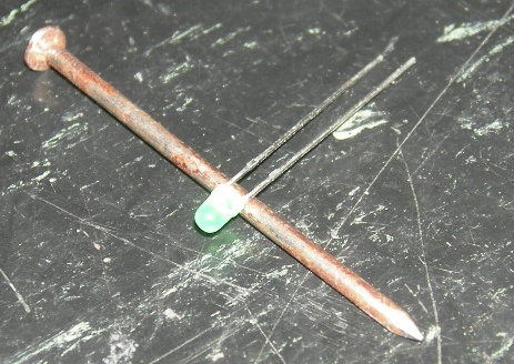
Bend the LEDs using a tool with around 2.5mm diameter.
Mind that the angle shoudl be around 80°
Take again care that the short end is on the left (here: top) side.
|
LEDs after bending
As the LEDs are laying here, the short pin is always on the left or the bottom. |
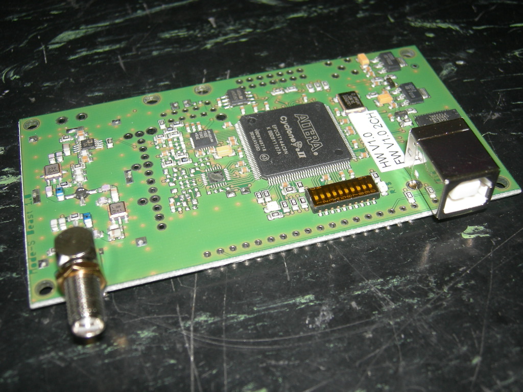
Next, you solder the SMA and the USB connector:
With a good soldering iron, solder the two connectors to the board. On the USB, also solder the two shield pins.
Do solder all pins of the connector including all ground pins.
Use the extra SMA hex nut fully down as distance holder of the front panel.
|

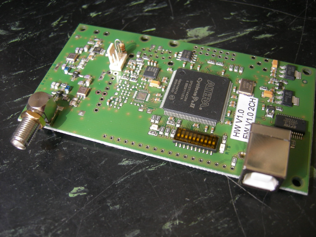
For the 2CH and the 4CH device, also solder the miniADSB connector and the 33R resistor (on 2CH one time, on 4CH three times).
|
|
Now mount the front panel
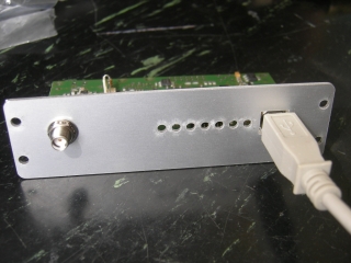
Mount the front panel.
Take care that a non-powered USB connector fits.
You might test if it fits into the box in order to find out that it needs some left or right shifting.
|
|
|
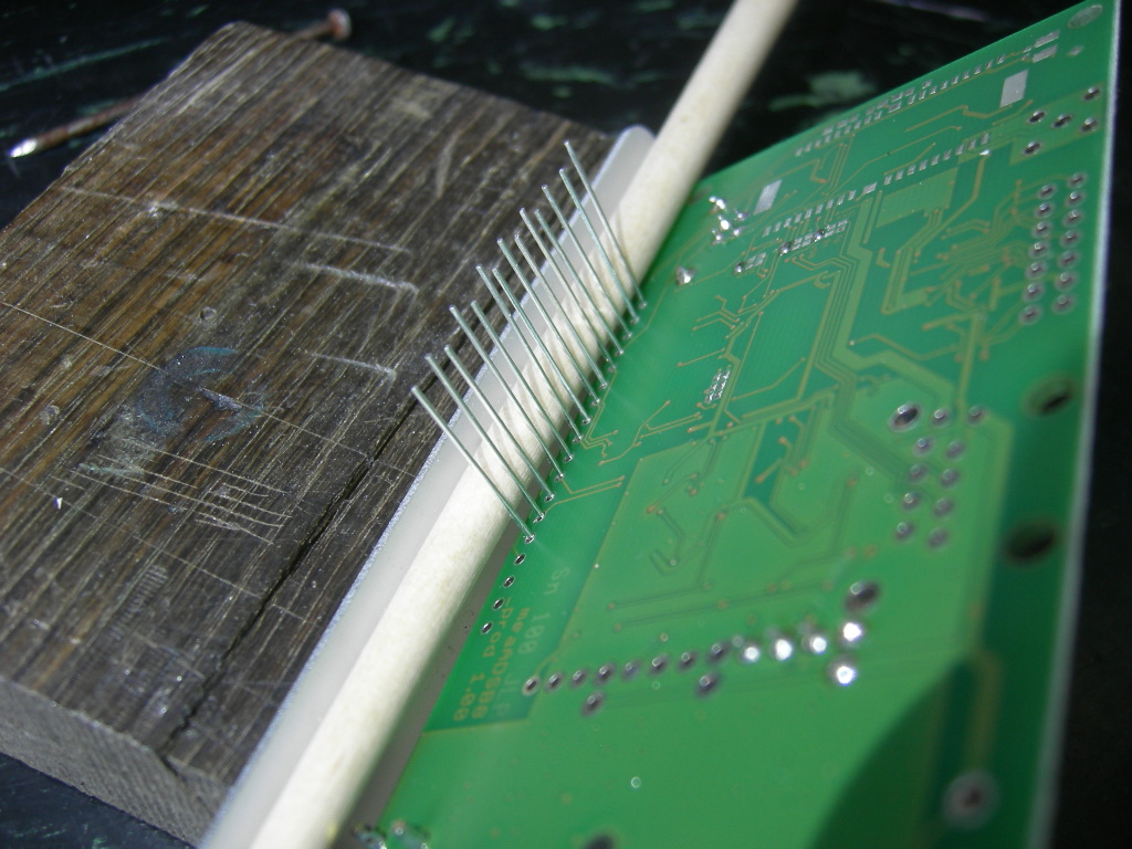
Insert and solder the LEDs
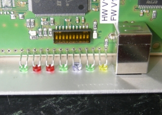
Insert the LEDs
Start with the blue LED, since this is a little bit larger.
Note that here on the photo the right yellow and right green LED are unfortunately swapped...
Insert the color scheme:
1CH: green - red - red - green
2CH: green - red - green -red
4CH: red - red - red - red
|

Fix the LEDs against the front panel, for example with a wooden stick (I've used a brush stick in the photo)
Solder the LEDs and cut the wires
In the background, right hand upper corner, you see the three solder
bridges that are necessary for USB RxD, USB TxD and USB RTS. I set them
during initial tests and they only need change if you intend to run it
via Lantronix Xport or BTM-222 Bluetooth
(HW Version 1.0)
|
|
Mount the assembly into the box
Mount the assembly into the box
glue the 4 feet to the under side of the box
|
|
And finally remember that there are also some solder bridges, which I
set up for USB operation prior to delivery. If you need others like the
Lantronix Xport or the BTM-222 Bluetooth, please read the bottom of the jumpers page.
Ready to be connected and tested