Theory of the DK7ZB-Match (new) The "classic" DK7ZB-Match  Full symmetrical 28-Ohm-Match by DF9IC "Sperrtopf" by DF7DJ

Bandwidth of some Amateurbands 

Band

Frequency Range

Bandwidth in %

70cm

430-440MHz

2,3%

2m

144-146MHz

1,38%

6m

50,0-50,3MHz

0,6%

10m broad

28,0-29,7MHz

5,9%

10m narrow

28,0-28,8MHz

2,81%

15m

21,0-21,45MHz

2,1%

20m

14,0-14,35MHz

2,5%

For a 3-El.-Yagi the following parameters are interesting:

1. Gain: High gain means narrow bandwidth, bad F/B-ratio and low impedance

2. F/B: High F/B means lower gain

3. Bandwidth/SWR: Great bandwidth means low gain and high impedance

4. Impedance:  - High impedance means great bandwidth, but low gain (50 Ohm)

                         - Low impedance means narrow bandwidth, but high gain (12,5 Ohm)

                         - Medium Impedance means medium bandwidth and medium gain (28 Ohm)

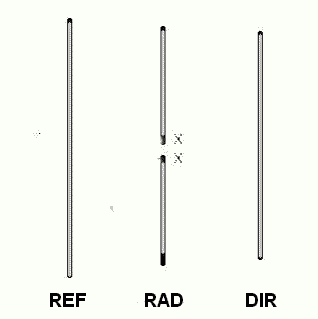
Attributes of 3-Element-2m-Yagis with  0,3l-Boom, Elements 6mm 

Please compare the table with the construction principles of a 3-El.-Yagi above


50 Ohm

28 Ohm

12,5 Ohm

SWR <1,5    6,7%

SWR <1,5    2,9%

SWR <1,5     1%

Gain 5,0 dBd, V/R 20 dB

Gain 5,6 dBd, V/R 24 dB

Gain 6,25dB, V/R 26dB

Pos.

Length

Diff.

Pos.

Length

Diff.

Pos.

Length

Diff.

Ref

0 mm

1041 mm

+4,8%

0 mm

1026 mm

+4,6%

0 mm

1022 mm

+4,5%

Rad

350 mm


-

275 mm

981 mm

-

220 mm

978 mm

-

Dir

600 mm

890 mm

-10,4%

600 mm

900 mm

-8,25%

600 mm

923 mm

-5,6%

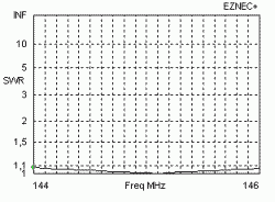
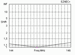
SWR 50-Ohm-Type

SWR 28-Ohm-Type

SWR 12,5-Ohm-Type

As you see ist the best impedance for the bandwidth of the most bands 25-30 Ohm and gives you a good balance of gain and F/B. This is the reason for the 28-Ohm-constructions.

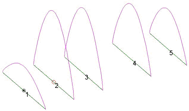
But what is with long Yagis? To understand that we look at the pictures below. A very good indicator for a Yagi structure is the element current profile.

For the 2-m-Yagis above and two further Yagi-groups with 0,2- and 0,41-lambda-boom I have calculated the data, here you can download the EZNEC-Files for your own modifications and comparsisons:

DOWNLOAD EZNEC-Files for 2-m-Yagis with 3 and 4 Elements

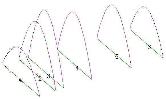
Element currents in a 5-El.-28-Ohm-2m-Yagi with 2,00m-Boom

The highest current is in the radiator, from the center the currents in the wave structure of the yagi are falling to the end slightly. If you have elements with lower currents in the structure, there is a failure in the contruction! This is the case for many older designs and the reason for bad patterns.

Now we try to change the design to an impedance of 50 Ohm. Therefore we need an additional "match-element" very close to the radiator. This element is not working as a classic director, it is an "open-sleeve-element", which has now the highest current in the yagi system.

We have replaced the one radiator (2) by two new elements ( 2 and 3). This system is very critical for the impedance trend and the pattern of the yagi. Why do that? My conclusion is the 28-Ohm-principle. All high-gain-long yagis with 50Ohm-impedance  have a significant lower bandwidth with slighly less or equal gain in comparison with the 28-Ohm-Yagis.

Element currents in a comparable (good designed!) 6-El.-50-Ohm-2m-Yagi with 2,00m-Boom

A lot of 50-Ohm-Yagis have a bad element current profile!

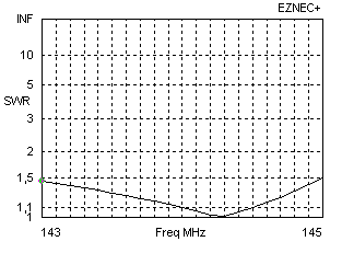
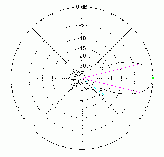
One of the best yagi designs for 2m I know is the 12-El.-28-Ohm-Yagi. Please look for the extrem clear pattern (no big backlobe and good sidelobes), gain 14,28dBd, bandwidth for SWR < 1,5 is 2 MHz!

You will not find any comparable yagi with the same boomlength, gain, pattern and bandwidth. It is impossible to match the antenna with the described match-element for a 50Ohm-direct feed. This is the reason why a lot of contest groups, EME-amateurs and severe DXers use homemade DK7ZB-yagis.

Horizontal pattern of the 12-Element-28-Ohm-Yagi at 144,3 MHz

 You can earn a box with 20 bottles of good German beer if you reach that aim to construct any comparable 50-Ohm-Yagi with 8m-boom, 14,28dBd gain, 2MHz bandwidth and such a clean pattern!

Here are some arguments and  questions you can hear about Yagis and my answers:

1. Medium impedance Yagis (28 Ohm) have losses

We had these arguments here in DL years ago, when I introduced my 28-Ohm-Yagis. People said, an antenna has to have 50 Ohm impedance (Why? Because the cable has 50 Ohm?). It took 5 years until the amateurs believed that it must not.

In the last ten years more and more “homebrewers” built thousands of that Yagis and in DL, SP, OM and OK the most contest crews with homemade antennas are running DK7ZB-28-Ohm-Yagis. And believe me, there are a lot of experienced hams who know what they do.

When you optimize a Yagi you must set the parameters for the optimizing conditions: Gain, bandwidth, pattern and impedance. I normally do not start with the impedance! A good compromize between the first three arguments does not lead to 50-Ohm-impedances automatically, in much cases an impedance around 30 Ohm is better.

Why no impedance match? Why should a short piece of two paralled 75-Ohm-coax cables cause more losses than a normal piece of coax as used in a half-wave-balun? When you construct a stacking harness for a H-frame with four 50-Ohm-Yagis you use quarter-wave transformation lengths to points of 25-Ohm-impedance. Do you believe in any mystic losses in that case? I do not.

2. OWA-Yagis are a better choice

If you prefer a wide bandwidth and lower gain, why not? But in most cases you do not need that. If you have a lot of  metal around the antenna your OWA-Yagi shows only a little influence to the SWR indeed. Great! But what you do not see is the distortion of your pattern and the reduced gain. Better is a clean surrounding of your antenna….. and then you can use a design with higher gain and better performance.

Real OWA-Yagis have a lot of elements on a smaller boom and can have 50 Ohm, but must not.

3. 50-Ohm-direct feed is better than a lower impedance

Do not believe that 50-Ohm-feed in a Longyagi means greater bandwidth! If you compare the magnitudes and phases of the currents in the radiator and the D 1 in a 50-Ohm-design you will see the cause for many problems: The close spaced first director is no real director, it has a much higher current than the radiator itself and that coupled system with “open-sleeve-principles” has severe influence to the pattern and the impedance across a greater part of the band (and losses, if you use a Flexa-Yagi with thin steel rods).

There are some new developments, which claim "50-Ohm-direct-feed", e.g. the LFA-Yagis by G0KSC. But these Yagis are low-impedance-Yagis, where the loop is the match from 12,5 to 50 Ohm. This has some advantage, because the impedance matching acts similar as with a horizontal folded dipole with a greater distance between the two parts.

An other way for a 50-Ohm-feed is a OWL-Yagi with 12,5 Ohm impedance and a folded dipole, which gives an impedance ratio of 1:4 and 50 Ohm.

So, what is "low-impedance"? Anay match device can transform to an impedance of 50 Ohm. This can be the quartewave-coax-cable solution, a folded dipole or a LFA-loop.