| Current Balun 1:1 | Broadband-Balun 1:1 | Balun 1:4 | Balun 1:1 + 1:4 | MTFT-Un-Uns | Endfed-Un-Uns 1:64 |
Un-Uns for Endfed-Antennas (EFHW) by DK7ZB
|
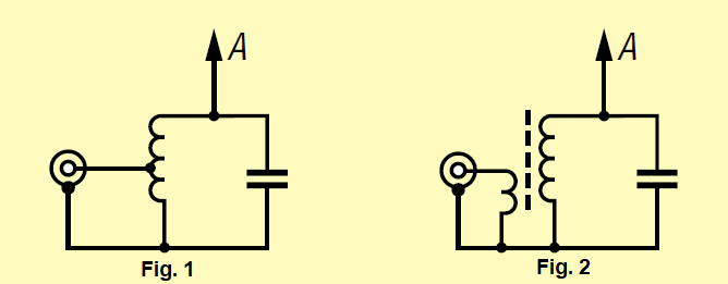
Wire antennas with an Un-Un-transformer 1: 9 have become more and more popular. This is based on random lengths of the antenna, which is transformed with the un-un into a medium-ohmic impedance range with reactive components. This can then, fed with coaxial cable, in many cases be tuned by the antenna matching devices ("ATU") built into the transceivers. However, it is better to use resonant lengths. This minimizes losses and creates clear resonance and impedance relationships. The classic end-fed half-wave antenna is a single-band antenna, known as the “Fuchs-Antenna” since the early days of amateur radio 90 years ago. For multi-band operation, it requires a switchable and tunable matching circuit. At that time, it was coupled directly from the anode circuit of the transmitter to the Fuchs circuit. Coaxial cables with 50 Ohm impedance are now used at the transmitter output, which requires a different supply. The coupling into the resonance circuit can either take place via a tap on the coil (Fig. 1) or some coupling windings ("link coupling") are used for this (Fig. 2). In any case, a voltage-proof variable capacitor is required for tuning. For high performance, this must have a plate distance of 4-5 mm. You can design the resonant circuit with a variable capacitor for two bands with a frequency ratio of 1: 2, e.g. 40/80 m or 10/20 m, but you still have to retune when changing bands. In addition, the larger capacity on the lower band contradicts the requirement for the highest possible LC ratio. |
|
With the help of toroidal cores it is now possible to create a high-resistance Un-Un for several bands. Such antennas, offered as commercial versions for some time, are marketed as "end-fed". This type of antenna is also ideal for inexpensive self-construction. The advantage of an end-fed half-wave radiator is that no feed cable with a balun in the middle of the antenna results in a considerable tensile load as with a dipole. This not only has mechanical advantages, the antenna wire is also much more inconspicuous to attach. Compared to the 1: 9 transformers based on the MTFT principle (Magnetic Transformer for Transmitting), which are usually incorrectly referred to as "magnetic balun" solutions, there are clear resonance ratios and fewer losses on the coaxial cable, which is better matched. While these antennas used to be called simply long-wire or Fuchs antennas in German, the English expression “EFHW” (End-Fed-Half-Wave) is increasingly being used. If you search the World Wide Web, you will not only find resonant half-wave antennas under the term “end-fed”, but also the radiators with random lengths fed by an MTFT-Un-Un 1: 9. These usually have three trifilar windings that are connected in series for transformation. Un-Uns with toroidal cores as a transformation element This is a step-up transformer with a winding ratio of 1: 7 to 1: 8. Since the impedances are entered here with the square of the ratios, one comes to the range of 3-4 KOhm if you provide 2 coupling and 14-16 decoupling turns. If you wind the toroid evenly, the high-resistance end comes very close to the coupling windings. If you leave a larger gap, the magnetic flux in the core may be uneven. In [1] it is suggested to switch to the other side after half of the turns in the manner of the W1JR balun. Coupling and decoupling are thus opposite one another. For me, the measurements also show that this solution seems cheaper. Since very high voltages occur at the output, it makes sense to use Teflon-insulated wire for PA services. I used it to build test samples. However, due to the distance between the coupling and transformer windings (due to the thickness of the insulation), the transmission seems to be insufficient. The SWR values achieved were worse on one side than with tightly twisted enamelled copper wire. The toroidal core is therefore wrapped with Teflon tape for higher performance. This can be obtained inexpensively from the building trade for sealing threads in the sanitary sector. Otherwise voltage flashovers at the core can occur at powers> 200 watts. |
|
|
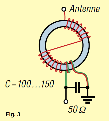
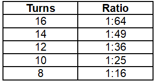
Since it is not a problem to tap the windings, several transmission ratios can be provided. The respective relationships are listed in Table 1. The basic scheme of the wrapping becomes clear in Figure 3. In order to achieve better adaptation to frequencies above 21 MHz, the two coupling windings should be twisted well with the first two windings of the secondary winding. I have also investigated a direct tap at the second turn. This results in a slight improvement at low frequencies, but it looks significantly worse for 15-10 m. A compensation capacitor of 100-140 pF has proven itself in the input. This should have a dielectric strength of 500 V for powers up to 100 watts, for higher powers the dielectric strength should be at least 1 KV. If necessary, you can connect 2x 220 or 2x270 pF / 500 V in series.
|
|
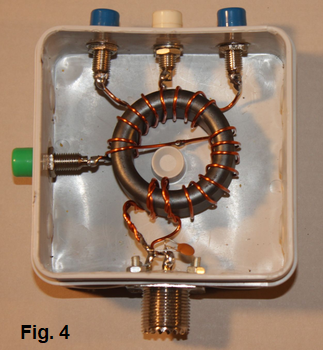
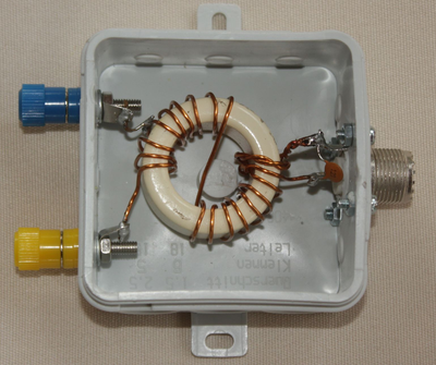
The transformer with the toroidal core FT140-43 In Fig. 4 you can see the toroidal core wound with 1.2 mm CuL wire. The two ends with 1:48 and 1:64 are intended for real half-wave antennas. With the other taps at, it is possible as MTFT (Magnetic Transformer for Transmitting) at 1:25 and 1:16 to also adapt random lengths with the help of antenna tuners. The mode of operation is based on a switchable Un-Un-MTFT already described in the FA. The best tap is determined through trials. The Un-Un created in this way was tested with powers of up to 150 watt HF in CW / SSB. |
|
|
|
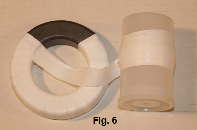 |
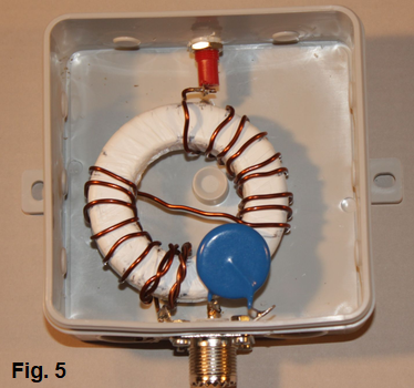
A Toroid with FT240-43 A core FT240-43 is used for higher outputs (Fig. 5). Here the core was insulated with PTFE-tape from the enamelled copper wire with a diameter of 1.5 mm. For this purpose, two layers of Teflon tape are applied. Since this is not that easy, the following method is recommended: The tape is previously applied to an auxiliary body that is smaller in diameter than the inner ring of the toroid. In this way, this auxiliary roller can be threaded through the inside, as shown in Figure 6. The transformer constructed in this way can easily handle 750 watts of HF. |
|
Un-Uns for higher frequencies The tests showed that the results for the 7-28 Mhz bands can be improved with a core of lower permeability. In Fig. 7 you can see an Un-Un with optional transmission ratios 1:49 or 1:64. This was carried out with a Ferroxcube toroidal core of the type TX36 / 23 / 15-4C65 from DX-Wire [3]. This is a structure up to 200 watt HF, there is also a correspondingly larger type for high power. The advantage of these toroidal cores is that they are coated with a high-temperature and tension-resistant lacquer, which makes wrapping with Teflon tape superfluous. Similar results should be achieved with the Amidon core material 61, but the types FT140-61 and FT240-61 do not have protective insulation and should therefore be made high tension-proof for high performance with Teflon tape.
|
 |
|
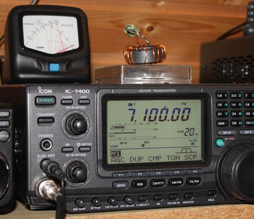
It is always good to make sure that a transformer is working properly before using it. An analyzer is ideal for this, but a functional test is also possible with a simple SWV measuring device. To do this, you close the output with 3x 10 KOhm resistors (metal oxide film resistors, 2 watts, connected in parallel). This can be loaded with significantly higher power for a few seconds to measure. Figure 8 shows this method. Here the prototype was tested with the FT140-43 (Fig. 4). With an IC-7400, 30 watts of HF were briefly applied to the load resistors. The SWR shows almost no retrace at 7.1 MHz. With a compensation capacitor, the adaptation curve can be improved at higher frequencies, especially in the 10 m band. However, the C must not be set too high, otherwise the SWV will noticeably deteriorate again in the 3.5-21 MHz range. After measuring with a variable capacitor, the determined capacitance is replaced by a fixed capacitor. With both versions with the FT140-43 and FT240-43, 120 pF turned out to be the best compromise value for me. The ceramic capacitor should have an electric strength of 500 V for 100 watts, for higher power it should be capable of carrying 1 KV. A series connection of two commercially available 500 V ceramic capacitors is possible. Theoretically, end-fed, high-impedance wires do not actually need a counterweight. Werner Schnorrenberg (DC4KU) made it clear in a report that this looks different in practice [3]. This article is required reading for anyone experimenting with half-wave antennas. The statements made there on the use of standing wave barriers to optimize adaptation and noise absorption can be fully confirmed. Failure to observe the advice given there can sometimes lead to unsatisfactory behavior with end-fed half-wave radiators. Some interesting observations can serve as an aid for your own experiments. If the antenna is high and freely suspended, a transmission ratio of 1:64 brings good results. In environments disturbed by houses, trees or masts, the impedances will obviously drop and a lower transformation ratio will give better matching. This was particularly noticeable with a sloper braced towards the ground, which showed the best SWV at 1:25 and, depending on the frequency, even at 1:16. However, the optimal length is also influenced by the tap selected. In any case, the Un-Us proposed here offer a wide field of activity for antenna experiments. The upcoming portabel season could be well suited for this. Sources: [1] Scheepers, J. (PD7MAA): Multiband End-Fed-Antennas from 3,5-30 MHz, http://pa-11019.blogspot.de/2012/04/149-transformer-for-endfed-antennas-35.html?m=1 [2]
https://www.dx-wire.de/ferriteringkerne/ringkerne-fuer-balunuebertrager/ringkern-tx362315-4c65.html [3] Schnorrenberg, W. ( DC4KU): Optimaler Betrieb einer endgespeisten Halbwellenantenne, FUNKAMATEUR (67) 2019, H. 4, S. 341-345
|