DK6ED DX-Loop
Magnetic
loop with improved radiation pattern for optimum DX reception in distorted
locations.
Basic ideas
Reception
can be realized by either analyzing the electric or the magnetic field radiated
by any source. This is important to know because in most cases local noise
sources are radiating the electric field by the mains or any electrical
network. Only after a distance of more than one wavelength the distorting
energy will be evenly distributed on the electric and the magnetic field. This
is why magnetic loops are recommended for use in distorted areas.
But, every
loop is made from a defined length of wire, picking up the electric field of
the noise source. So the circumference of the loop must be limited. Because of
this limitation, magnetic loops are not sensitive enough for convincing DX
reception on low frequencies. By introducing a current amplifier, suppressing
the voltage picked up, it is possible to extend the circumference of any loop.
This is the first advantage of the new proposed design. Another point is the
fact that magnetic loops are having two minima and two maxima. To suppress a local
noise source only a single minimum is needed. On the other hand the maximum
should be as broad as possible for all-round reception. This is exactly the
pattern of radio direction finding (RDF) antennas. But these systems are very
small using resonant loops. So a new design has to be introduced for the
antenna also.
New antenna
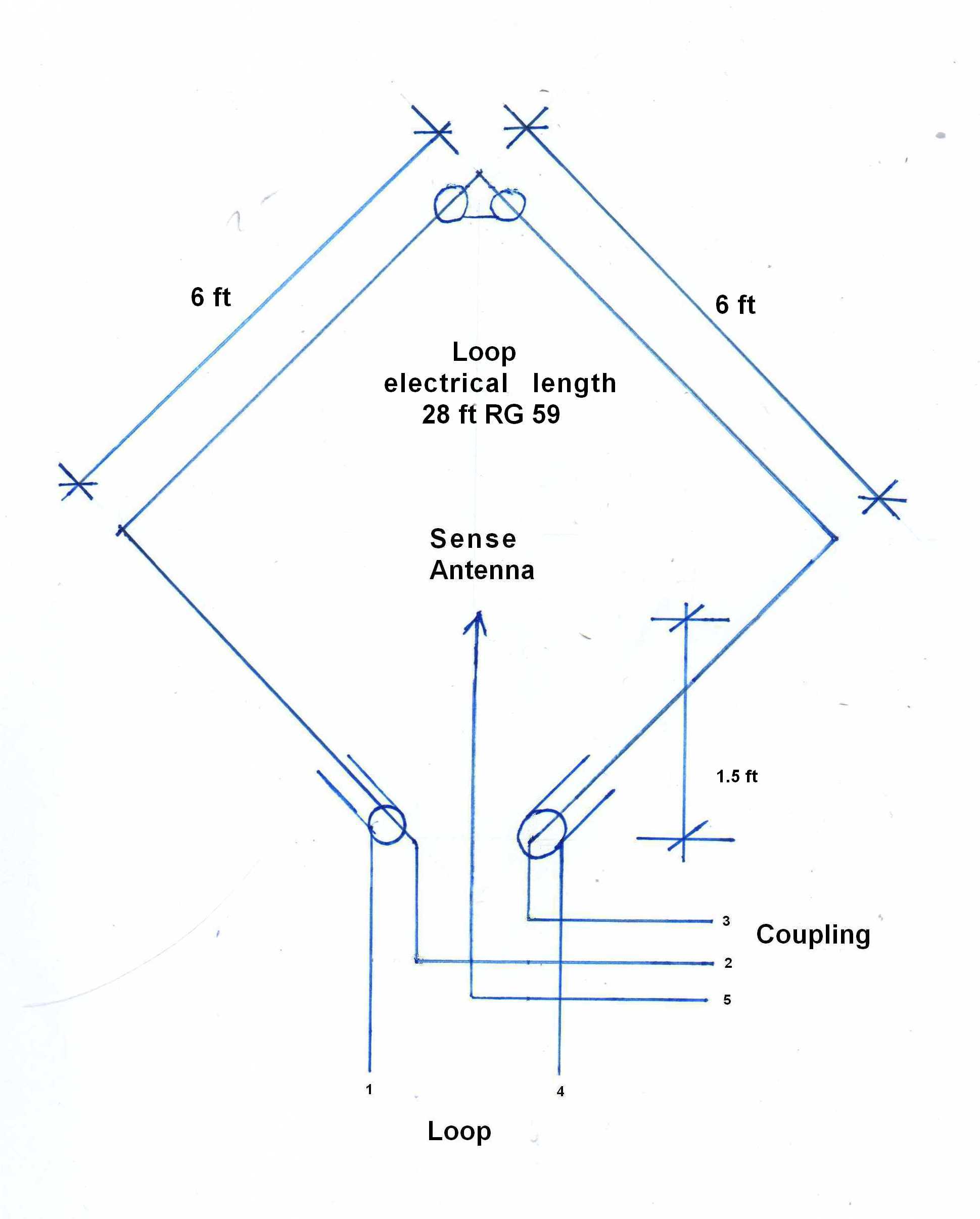
The new
antenna system consists of a large loop made from coax and a sense antenna.
This
results in a very broad horizontal pattern over a wide frequency range:

The
vertical pattern:
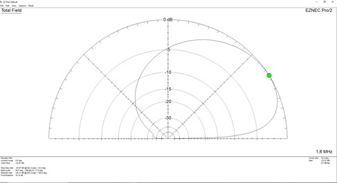
This is the
way to reduce local interference.
New
preamplifier
The signal of
the loop is fed to a newly designed current amplifier, suppressing any voltage
input. It consists of a combination of a common source and a common drain stage.
Common source circuits shift the phase of the signal, common drain circuits do
not. When combining these two stages, the voltage signal will be extinguished.
But due to the different current gain of the stages, the amplifier still offers
a convenient gain. For the sense antenna another drain stage will be
implemented. Its output is fed into the center lead of the coax loop.

The
amplifier is connected through a choked coax line to the receiver. Choking the
line is most important to avoid any strew in distorting the pattern from the
backside.
Results:
My main
interest is DXing on the low amateur radio bands 80 / 160 m on my small lot.
Experimenting with receive antennas led to 310 DXCC on 80 m and 272 DXCC on
160m. In my location the new antenna system improves the signal-/noise ratio
significantly.
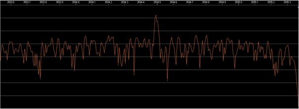
To show the
results, a transmit vertical antenna is compared to the proposed loop system. The
loop is installed at a distance of 30 ft. from the local noise source. The
receiver bandwidth is set to 4.7 KHz. The following diagrams show the
difference in SNR receiving the signals of a beacon on 80 m.
This is the
signal on the transmit vertical:
This is the
same signal on the receive loop:
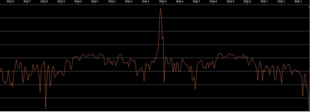
This leads
to an improvement of SNR of more than 20 dB.
Even on the
very small bandwidth mode FT8 improvements up to 10 dB were experienced.
Tests were
made with even larger loops covering an area of 400 ft2. These
systems are more sensitive but still all local noise was suppressed.