
A 360º ANTENNA DIRECTION INDICATOR
With absolute BCD encoder
By CU8AO
Here you will find the description af an antenna indicator i have designed.
The idea was to make it really simple, with no hard-to-find parts,no programmable components,and using an absolute encoder,that will not loose its memory when powered off, and really accurate.
Obviously,the same design can be used for elevation.In that case, just a 90º or 180º potion of the disk is used.
Costs are reduced to a minimum.The most expensive parts here are the PCB´s!
Please keep in mind that the main purpose was to be SIMPLE,it is not perfect.You will probably find improvements and adjustments necessary or usefull.
The mains disadvantage of this design is that you will need a 12 conductors cable between antenna and the shack.This is no big deal if you can find cheap telephone 6-pairs cable,for example.
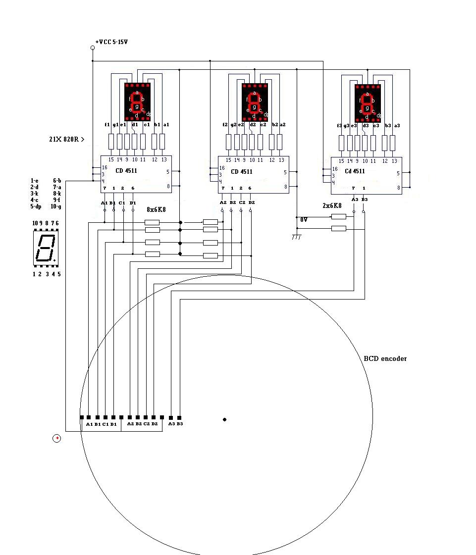
The schematic diagram is shown below:
Schematic diagram:
Parts needed:
-ICs : Cd 4511.............................................................3
-Resistors 1k2R ........................................................21
-Resistors 6k8 ..........................................................12
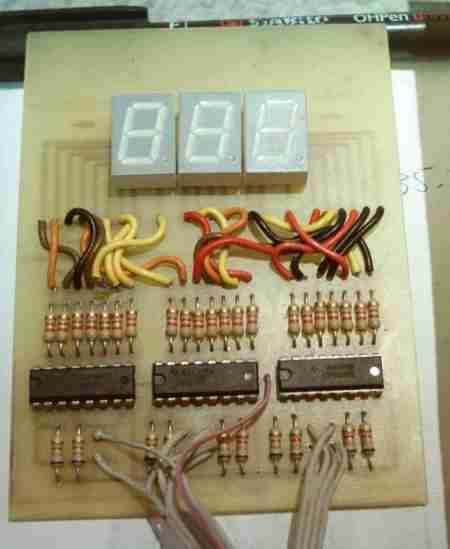
-Common cathode 7 segments led displays:.......3
PCB : 18X18cm for encoder and 8X8cm for display board(s)
Cable and wire.
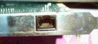
Female telephone connector,for the contacts.
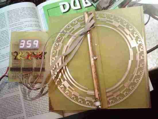
PCB of the encoder:
It is quite a large PCB, as the diameter of the disk is 18cm.This was to give a spacing between tracks of 2.54mm,(allowing the use of readily available connectors and easier soldering ) and give more tolerance to misaligment and etching defects.Of course, you can do it any size if you need it more compact.
Click on the picture to download the full size design (932kb)

To print the PCB, you should make it such a way that finished diameter is 178mm.If you are using Acdsee,check "fit to size"and set margins to 0.1".
Three of the tracks are common,this was to allow good connection to the +vcc.They should be connected together, and only one wire will bring the supply.Ground (0V) is not present.
LED display driver PCB:
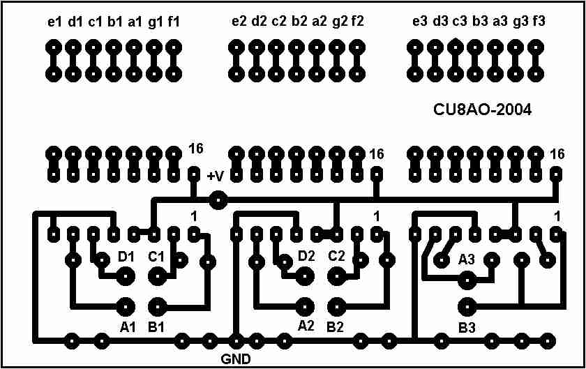
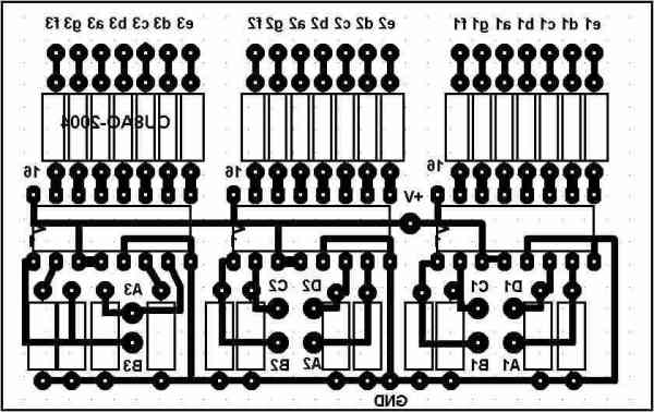
Display driver PCB.Click to download.Size is 46X74mm. Components side
As it can be seen on the schematic, it make basic use of the 4511 Ic´s ; each imput is forced to ground by a 6k8 resistor.Value is not critical at all.The outputs are connected to 820r resistors, to limit the current in the LED displays.This value should be modified if another supply voltage is used.
Led display PCB:
The display is made with 3 common cathode 10 pins led displays.
Here is the PCB:

size is 74X33mm
I have choosed to make this PCB to connect to the driver PCB by wires.This allow a simpler pcb design,and it will fit in a wider range of enclosures, at the expense of some work to solder each wires one by one.Obviously,one can make both PCB on the same board.
Contactor PCB´s:
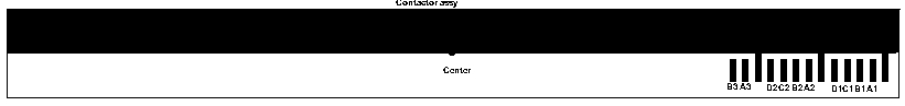
Size is 180X20mm
Drill 0.8mm holes in the center of the pads.
On top of this PCB, is soldered another one at 90º to reinforce it.You will not need to etch this one, just cut and solder.

Size:180X13mm. the slot in the center is for the head of the screw.
This is similar to a compass needle.In one end are 13 pads to allow soldering of the small spring contacts,removed from a female telephone type connector.You can find such connectors in (some)old telephone sets,modem or network cards, cheap adapters to connect more than one telephone on your line, etc.The contacts are carefully heated with a soldering iron and removed.Then they are bend this way:

This is the tricky part : you now have to solder each contact carefully.The hole in the center of the disk must be perfectly centered.Check with a compass before drilling.This is very important.
After the encoder is completed,verify that it is working fine.You should read from 000 to 360 in 1 increments.You will have to readjust the contacts in the longitudinal plane with a small screwdriver, if you see jumps in the increments.The BCD code is as follow:
oooo ooox ooxo ooxx oxoo oxox oxxo oxxx xooo xoox ( The "X" means a contact)
0 1 2 3 4 5 6 7 8 9
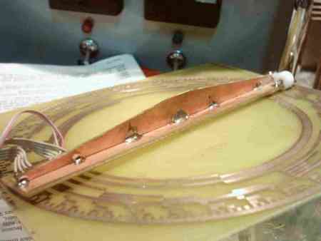
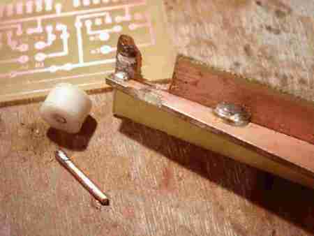
The screw is soldered in place before the vertical pcb. Optional:a small teflon rod removed from an old N female chassis connector
make a nice end wheel.use a small piece of rigid wire soldered for the shaft.

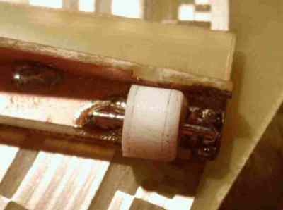
Contacts detail. Opposite to the contacts, a small weel will allow to make pressure without damaging the PCB.
Depending on your instalation,you can bolt the "needle" of the encoder on the mast or the tower, for example with an "L" shaped piece of aluminium.Then it is the disk that rotates, either directly connected to the antenna, or by the mean of a small stainless steel fishing cable,as i have done with mine.
Possible inprovements:
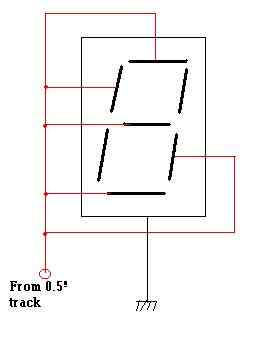
-By adding another track on the outside of the disk,with 0.5 deg separation and equal width,and just adding one more wire from the tower,it is easy to double the precision of this display.Just connect the fourth display like this :
Attention,i have forgotten in the diagram below to mention the limiting resistors.I can be five 1k2 resistors,but one 220R 1W resistor in the wire should work too.
Finished :
If you build this indicator, please i would like to know the results and eventuals improvements.
Back to home Email:microwave(at)clix.pt