PTT SWITCHING CIRCUITRY
This is the most
complex part of the system, it provides information to all the parts about VOX
activity, PTT information status and response transmisson to the activacting
station
..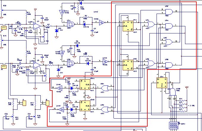
The signal from the VOX sets de DATA IN flip-flop to a logic high to enable the PTT, this signal get´s out of the flip-flop after one clock cicle, locking the other flip-flop to a low state disabling like this the receiving radio PTT. This signal is then driven to the or gate U7 that is also used to set the PTT on for the response transmisson, after U7, U9 set´s the PTT on, U9 is used to turn PTT off, if the maximum continuos time on air is reached ( see timing section ). When the VOX get´s low there is a time window at the flip-flop were the DATA IN and negated Q are low, at this time, U8 or U7 ( depending on the channel ) get´s low and a response PTT is generated by the timing cicuit ahead, ( U24, D4, C........ ) and this signal activates the PTT via U7. The control flags are generated at U9C pin 10 ( BUSY active low ), on U7C ( BUSY Active high ).